Surgical manipulator for a telerobotic system

a telerobotic system and manipulator technology, applied in the field of surgical manipulators, can solve the problem that the actuation force applied by the drive motor will not generate any effective side loads on the instrument, and achieve the effect of convenient sterilization and convenient design of the telerobotic system

Inactive Publication Date: 2005-09-01
SRI INTERNATIONAL
View PDF5 Cites 51 Cited by
  • Summary
  • Abstract
  • Description
  • Claims
  • Application Information

AI Technical Summary

Benefits of technology

[0010] In a specific configuration, the support base includes a frame with distal and proximal support members and a pair of shafts rotatably mounted within the support members. The instrument holder is slidably mounted on the support shafts for axial movement of the instrument. In addition, the shafts are each coupled to a drive motor for providing the instrument with second and third degrees of freedom, e.g., rotation and end effector actuation. The drive motors are coupled to the proximal support member so that they will not be contaminated during surgery. The rotatable shafts can be removed by sliding them upward and out of engagement with their lower bearings and the instrument holder so that the instrument holder can be easily removed from the support base for sterilization. The lower portion of the support base (including the distal support member) may also be sterilized to decontaminate those parts that have contacted the instrument holder. In this manner, the surgical manipulator can be easily sterilized after a surgical procedure without damaging the servo motors or the electrical connections required for the telerobotic system.
[0011] The support base further comprises a sleeve, such as a cannula or trocar sleeve, mounted on the distal support member. The sleeve has an axial passage for receiving the instrument therethrough and a force sensing element mounted within the axial passage near the distal end of the sleeve. The force sensing element is configured to detect lateral forces exerted on the element by the distal portion of the instrument during surgery. Since the force sensing element is mounted distal to the remainder of the apparatus, it is undisturbed by forces that may be exerted on the cannula by the surgical incision or by gravity and inertial forces that act on the instrument holder. When supported by a positioning device, the surgical manipulator can be used with an inclinometer to determine the true orientation of the instrument holder with respect to the direction of the local gravitational field. Use of the inclinometer and force sensors with the manipulator facilitates the design of a telerobotic system in which the surgeon will directly sense the forces acting against the end of the instrument, unaffected by extraneous forces acting on the telerobotic mechanism. In other words, the surgeon will feel as if his / her hands are holding the instrument at the point in which the instrument contacts the force sensing element.

Problems solved by technology

Since the force sensing element is mounted distal to the remainder of the apparatus, it is undisturbed by forces that may be exerted on the cannula by the surgical incision or by gravity and inertial forces that act on the instrument holder.
Because of the symmetrical design of the helical actuator, the actuation force applied by the drive motor will not generate any effective side loads on the instrument, which avoids frictional coupling with other degrees of freedom such as axial movement and rotation of the instrument.

Method used


Image

  • Surgical manipulator for a telerobotic system
  • Surgical manipulator for a telerobotic system
  • Surgical manipulator for a telerobotic system

Examples


Embodiment Construction

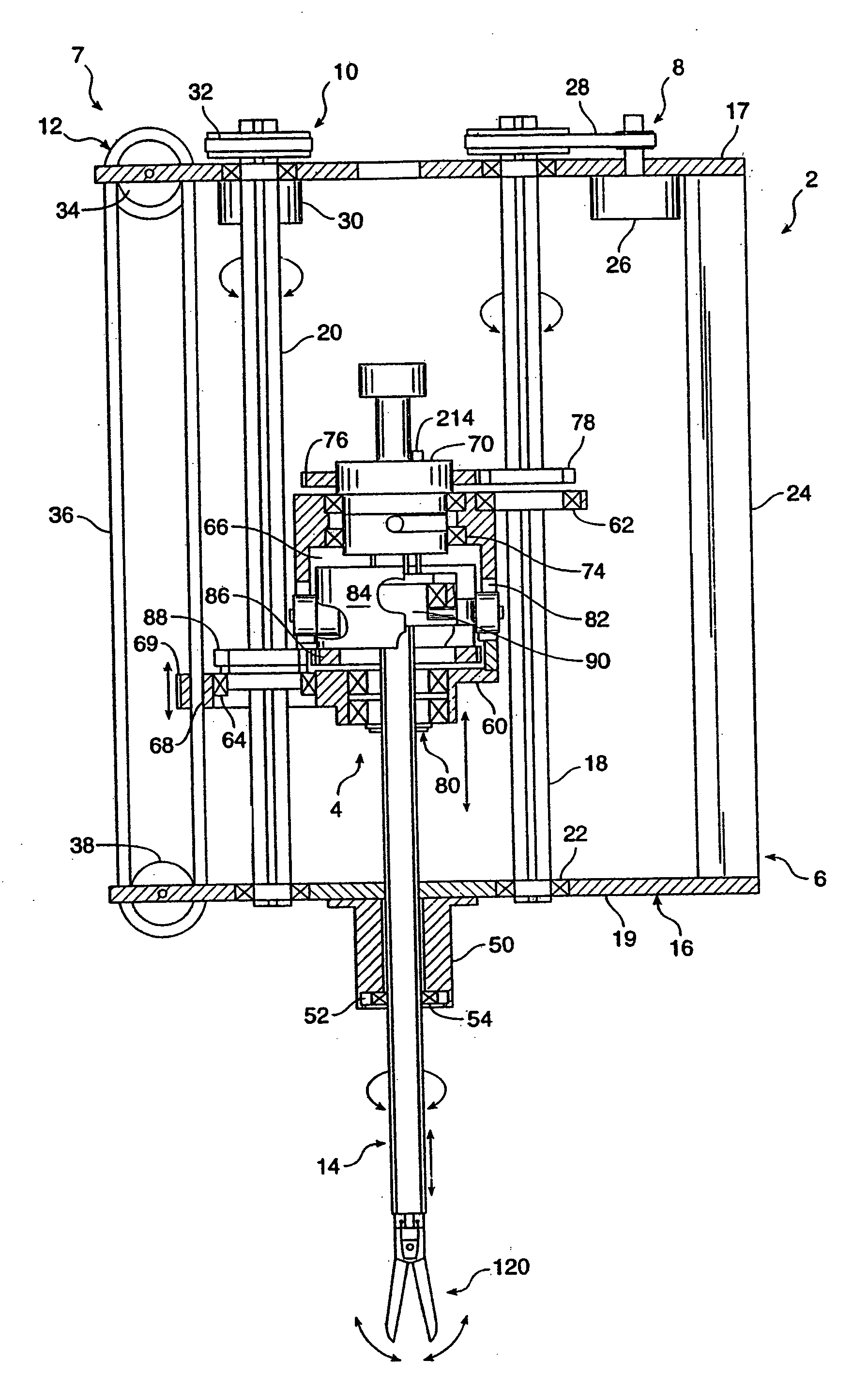
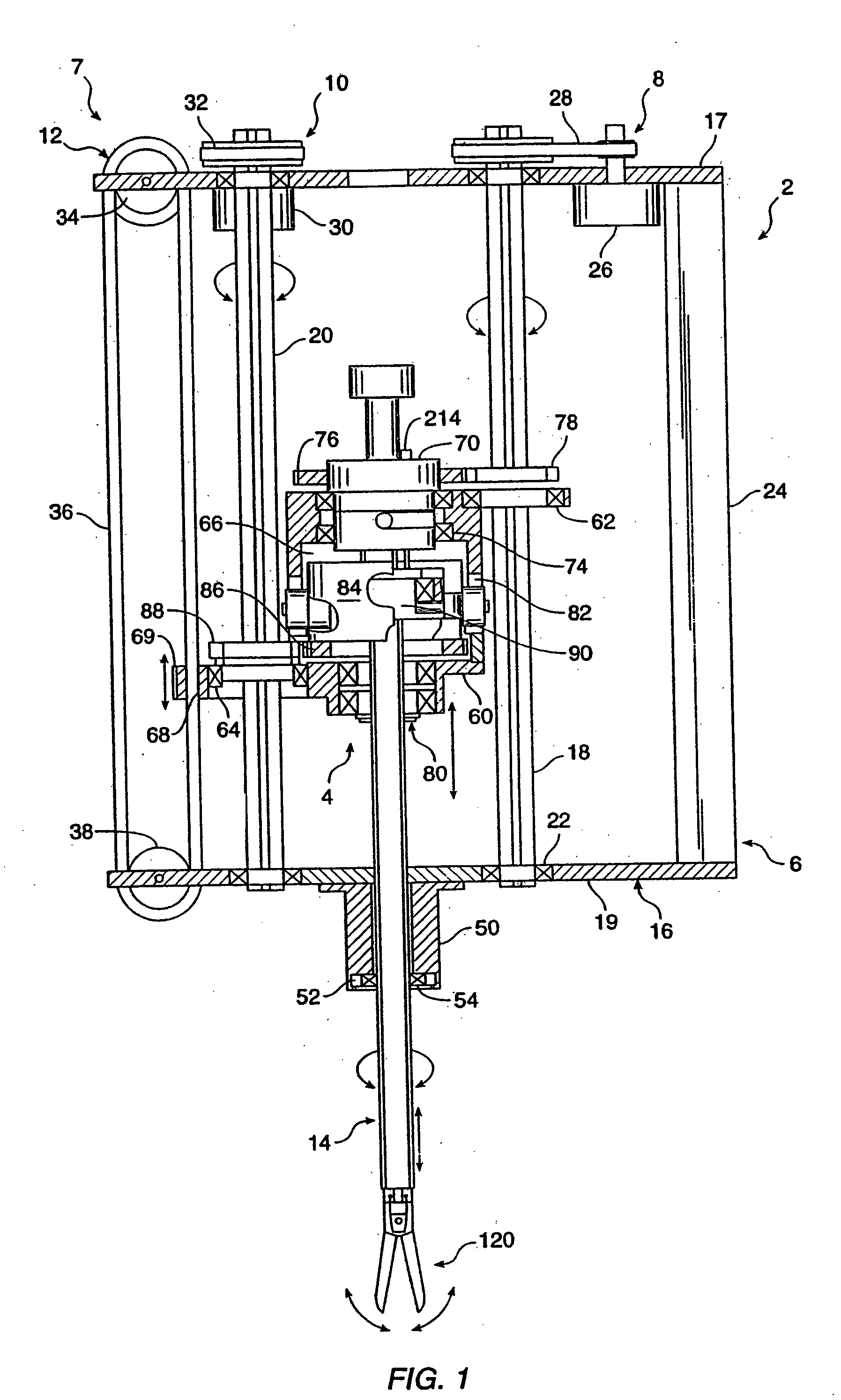
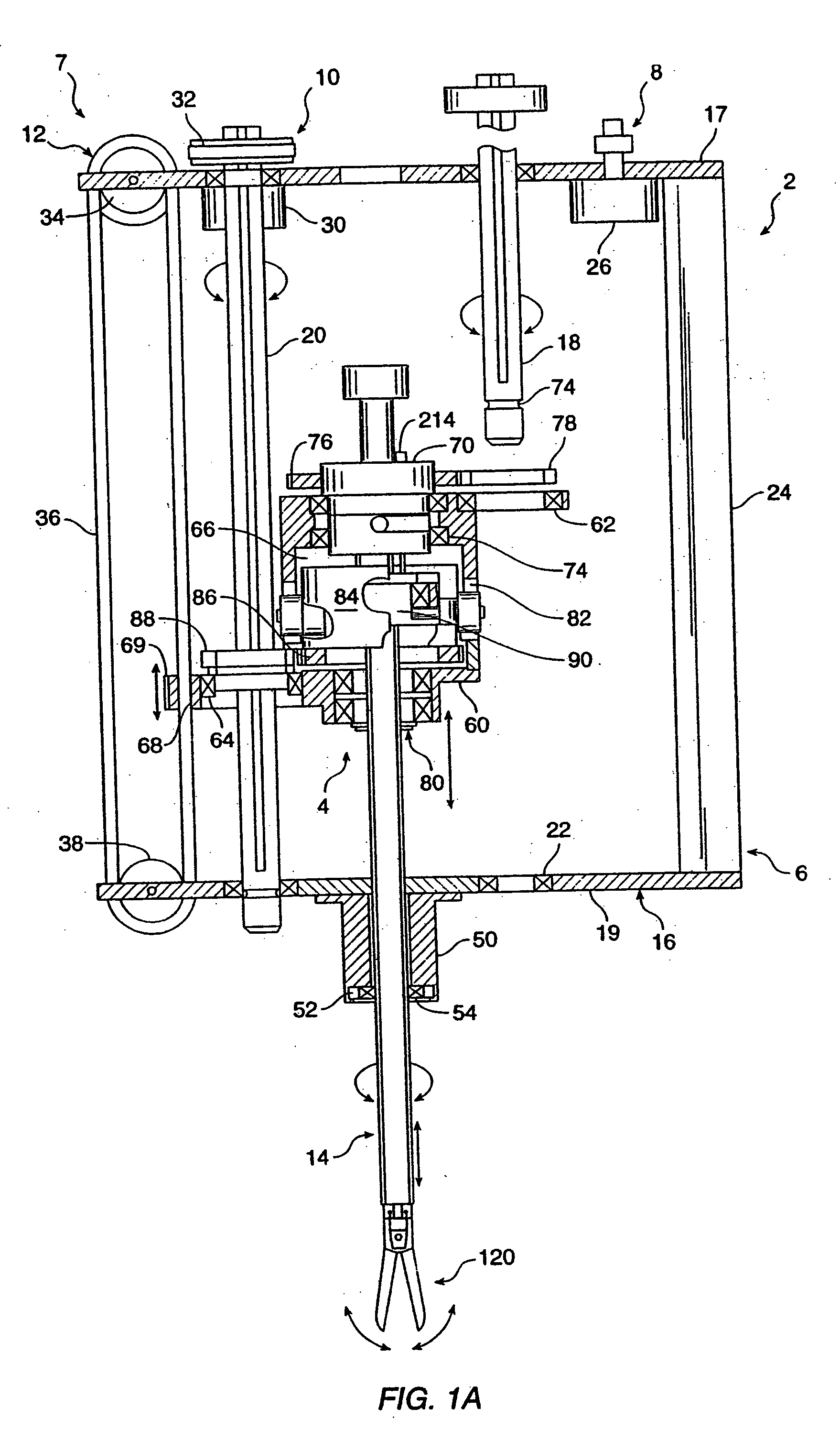
[0024] Referring to the drawings in detail, wherein like numerals indicate like elements, a manipulator assembly 2 is illustrated according to the principles of the invention. Manipulator assembly 2 generally includes an instrument holder 4 removably mounted to a base 6 and a drive assembly 7 for manipulating a surgical instrument 14 releasably coupled to instrument holder 4.

[0025] Referring to FIG. 1, base 6 comprises a frame 16 having proximal and distal elongate support members 17, 19 and first and second ball-spline shafts 18, 20 rotatably coupled to support members 17, 19 via bearings 22. Frame 16 further includes a support bracket 24 for attaching manipulator assembly 2 to a remote center positioner 300, as discussed in more detail below (see FIG. 9). Drive assembly 7 comprises first, second and third drives 8, 10, 12, which are mounted to frame 16 and configured to provide three degrees of freedom to surgical instrument 14. In the preferred embodiment, first drive 8 rotates ...


PUM


Abstract

The invention is directed to mainpulator assembly (2) for holding and manipulating a surgical instrument (14) in a telerobotic system. The assembly comprises a base (6) fixable by passive or power driven positioning devices to a surface, such as an operating table, and an instrument holder (4) movably mounted on the base. The instrument holder comprises a chassis (6) and an instrument support (70) movably mounted on the body and having an interface engageable with the surgical instrument to releasably mount the instrument to the instrument holder. A drive assembly (7) is operatively coupled to the instrument holder for providing the instrument with at least two degrees of freedom. The instrument holder is separable from the base and the drive assembly so that the holder can be sterilized. The assembly further includes a force sensing element (52) mounted distal to the holder and the drive assembly for detecting forces exerted on the surgical instrument and providing feedback to the surgeon. The assembly is attached to a remote center positioner (300) for constraining the instrument to rotate a point coincident with the entry incision and an inclinometer (350) for preventing gravitational forces acting on the system's mechanisms from being felt by the surgeon.

Description

CROSS-REFERENCES TO RELATED APPLICATIONS [0001] This application is a divisional of and claims the benefit of priority from U.S. patent application Ser. No. 09 / 104,935, filed Jun. 25, 1998; which is a continuation of U.S. patent application Ser. No. 08 / 824,977, field Mar. 27, 1997; which is a continuation of U.S. patent application Ser. No. 08 / 487,020 filed Jun. 7, 1995, the full disclosure of which are incorporated herein by reference.BACKGROUND OF THE INVENTION [0002] This invention relates to surgical manipulators and more particularly to robotically-assisted apparatus for use in surgery. [0003] In standard laparoscopic surgery, a patient's abdomen is insufflated with gas, and trocar sleeves are passed through small (approximately 1 / 2 inch) incisions to provide entry ports for laparoscopic surgical instruments. The laparoscopic surgical instruments generally include a laparoscope for viewing the surgical field, and working tools such as clamps, graspers, scissors, staplers, and n...

Claims


Application Information

Patent Timeline
Patent Type & Authority Applications(United States)
IPC IPC(8): A61B17/00A61B17/28A61B17/34A61B19/00B25J3/04B25J15/04B25J18/04
CPCA61B17/29Y10T403/581A61B19/2203A61B19/26A61B2017/3445A61B2019/2211A61B2019/223A61B2019/2234A61B2019/2242A61B2019/265A61B2019/4868B25J3/04B25J15/04B25J18/04A61B2017/00477Y10T403/587A61B19/22A61B2090/506A61B34/70A61B34/71A61B2034/301A61B90/50A61B34/30A61B34/35A61B2034/305A61B2090/0813F16B2200/71F16B2200/69
Inventor GREEN, PHILIP S.JENSEN, JOEL F.
Owner SRI INTERNATIONAL
Why Eureka
Try Eureka