Loose-leaf type storage apparatus

Inactive Publication Date: 2005-09-08
CHEN-SOURCE INC
5 Cites 5 Cited by

AI-Extracted Technical Summary

Problems solved by technology

Because each pocket of the loose-leaf type storage apparatus A is not sealable, the storage item tends to be covered with dust.
When used with a ring binder, the periphery of each mounting through hole A3 may easily be torn, thereby causing the ...

Method used

[0028] 3. The loose-leaf type storage apparatus 1 can be integrally molded from plastics to reduce the cost. In this cas...

Benefits of technology

[0009] The present invention has been accomplished under the circumstances in view. It is therefore the main object of the present invention to provide a loose-leaf type storage apparatus, which holds the storage items firmly in place, protecting the storage items against scratching. It is another object of the present invention to provide a loose-leaf type storage appar...

Abstract

A loose-leaf type storage apparatus formed of two hinged shells each having a flat receiving space for receiving a disk-like storage item and a retainer for securing the loaded disk-like storage to the flat receiving space, one shell having a mounting strip with mounting through holes extended from the periphery for fastening to a ring binder.

Application Domain

Technology Topic

Image

  • Loose-leaf type storage apparatus
  • Loose-leaf type storage apparatus
  • Loose-leaf type storage apparatus

Examples

  • Experimental program(1)

Example

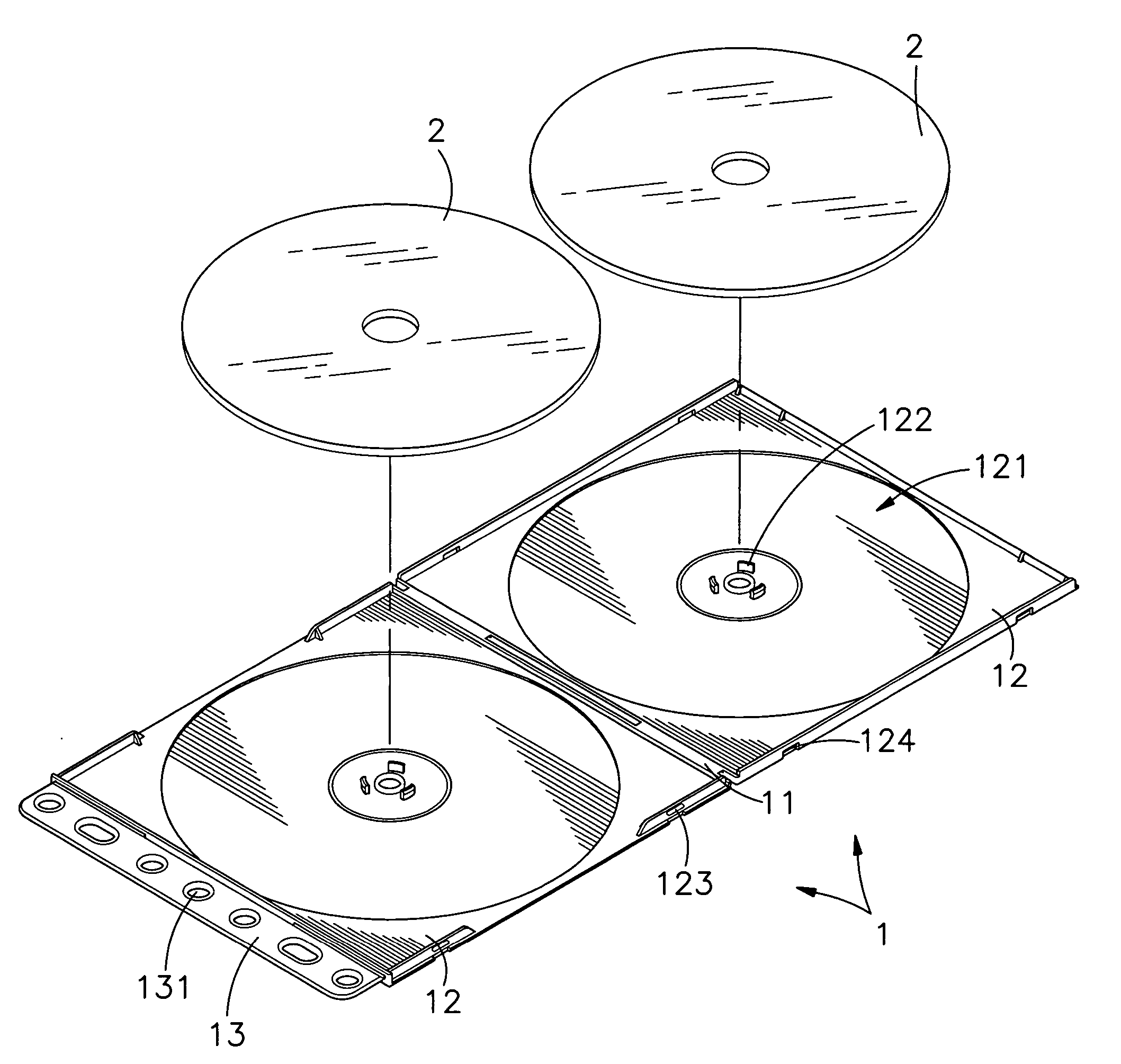
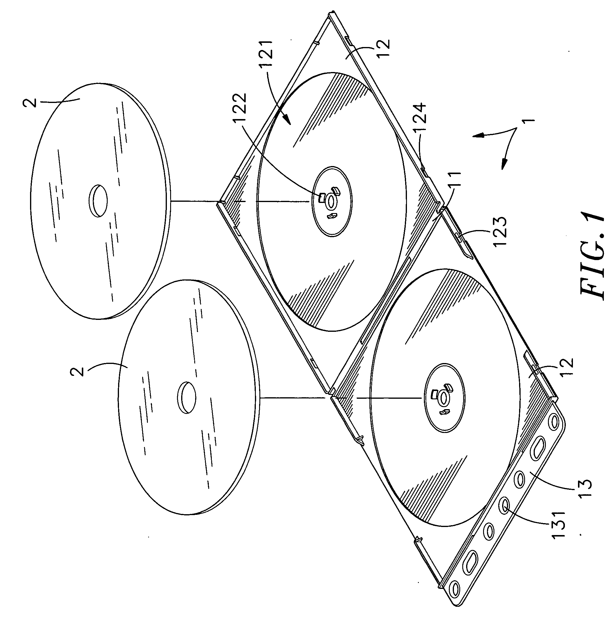
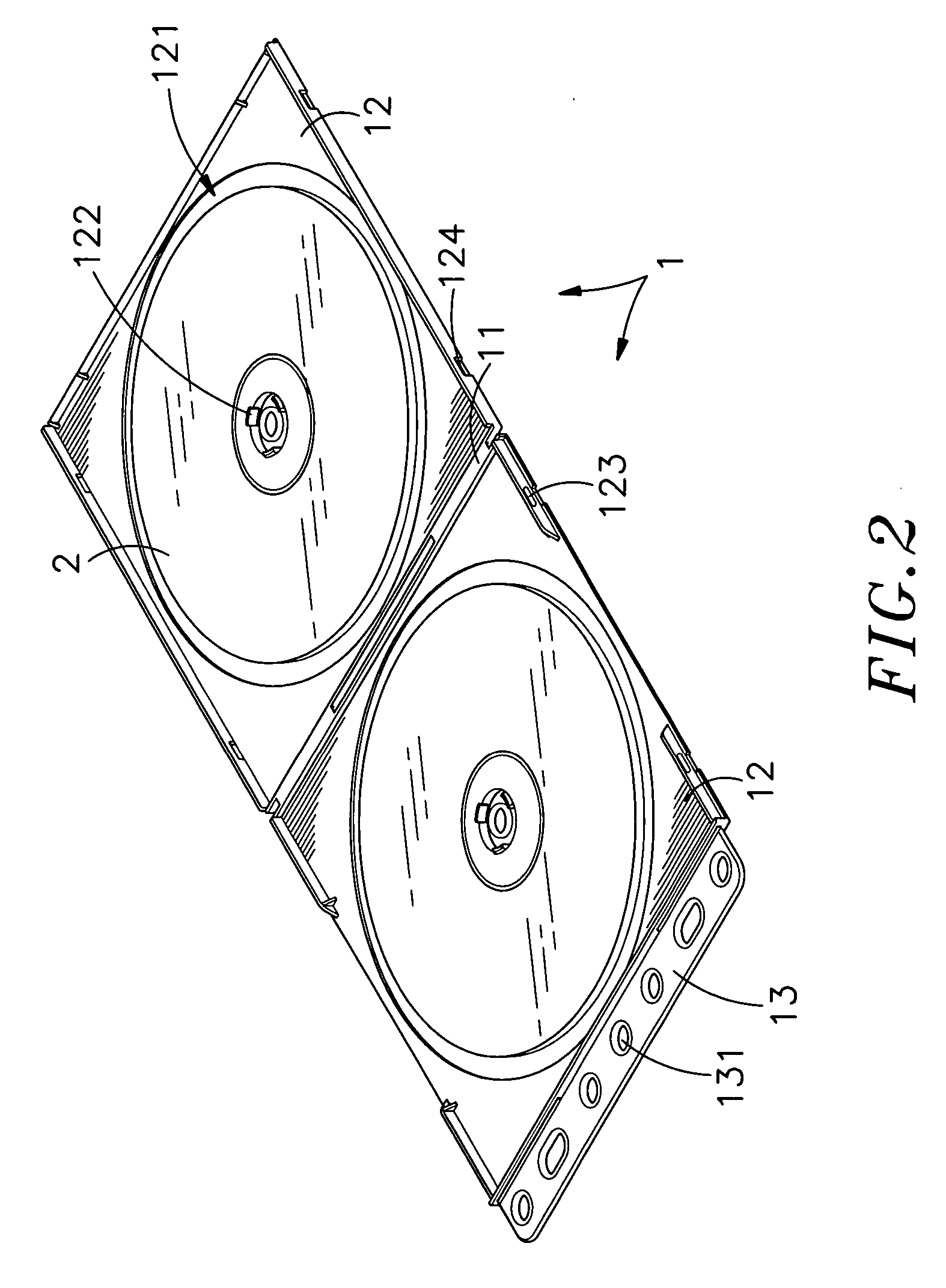
[0019] In FIG. 1, a loose-leaf type storage apparatus 1 is shown according to one embodiment of the present invention. The loose-leaf type storage apparatus 1 comprises two symmetrical shells 12, and a hinge 11 connected between the shells 12 for enabling the shells 12 to be turned relative to each other between a close position and an open position. The shells 12 each define a flat receiving space 121 adapted to accommodate a CD (compact disk) 2 or the like, and a retainer 122 disposed at the center of the receiving space 121 and adapted to hold a CD 2 or the like in the receiving space 121. One of the shells 12 has a narrow elongated mounting strip 13 extended along one peripheral side opposite to the hinge 11, and a plurality of mounting through holes 131 formed in the narrow elongated mounting strip 13 and arranged in a line. The loose-leaf type storage apparatus 1 further comprises a locking device formed of a male locking element, for example, a retaining flange 123, and a female locking element, for example, a retaining groove 124. The retaining flange 123 and the retaining groove124 are respectively provided at the shells 12.
[0020] Referring to FIGS. 2 and 3 and FIG. 1 again, after loading of a CD 2 in the receiving space 121 of each of the shells 12 and secured thereto by the respective retainer 122, the two shells 12 are closed to force the retaining flange 123 into engagement with the retaining groove 124, and therefore the loose-leaf type storage apparatus 1 is closed in the closed position.
[0021] Referring to FIG. 4, by means of the mounting through holes 131, the loose-leaf type storage apparatus 1 is fastened to a ring binder 3.
[0022]FIG. 5 shows an alternate form of the loose-leaf type storage apparatus. According to this embodiment, the loose-leaf type storage apparatus 1 comprises two mounting strips 13 spaced at one side, each mounting strip 13 having a plurality of mounting through holes 131.
[0023]FIG. 6 shows another alternate form of the loose-leaf type storage apparatus. According to this embodiment, the shells 12 of the loose-leaf type storage apparatus 1 have a circular shape, and one of the shells 12 has two mounting strips 13 extended from the periphery and linked to the hinge 11 at two sides. The mounting strips 13 each have one mounting through hole 131.
[0024] The loose-leaf type storage apparatus 1 can be made from plastics in integrity. Preferably, the shells 12 can be made transparent or semi-transparent so that the user to see the storage item(s) in the loose-leaf type storage apparatus 1 without opening the shells 12.
[0025] As indicated above, the loose-leaf type storage apparatus of the present invention has the following features:
[0026] 1. By means of the retainer 122 in the receiving space 121 of each of the shells 12, the storage item (CD) is held firmly in the receiving space 121 and well protected by the respective shell 12.
[0027] 2. The hinge 11 enables the shells 12 to be turned relative to each other between the open position and the close position. When closed, the storage item is well protected against dust.
[0028] 3. The loose-leaf type storage apparatus 1 can be integrally molded from plastics to reduce the cost. In this case, fastening the mounting through holes 131 to a ring binder 3 does not cause the mounting strip(s) 13 to break easily.
[0029] A prototype of loose-leaf type storage apparatus has been constructed with the features of FIGS. 1˜6. The loose-leaf type storage apparatus functions smoothly to provide all of the features discussed earlier.
[0030] Although particular embodiments of the invention have been described in detail for purposes of illustration, various modifications and enhancements may be made without departing from the spirit and scope of the invention. Accordingly, the invention is not to be limited except as by the appended claims.

PUM

PropertyMeasurementUnit
Transparency
tensileMPa
Particle sizePa
strength10

Description & Claims & Application Information

We can also present the details of the Description, Claims and Application information to help users get a comprehensive understanding of the technical details of the patent, such as background art, summary of invention, brief description of drawings, description of embodiments, and other original content. On the other hand, users can also determine the specific scope of protection of the technology through the list of claims; as well as understand the changes in the life cycle of the technology with the presentation of the patent timeline. Login to view more.

Similar technology patents

Swimming aid device

ActiveUS20090053947A1Easy and inexpensive to manufactureMinimizes and negates needSwim finsEngineeringAssistive device
Owner:NGUYENOVATION INC

Lithium secondary battery negative electrode active material and method for manufacturing same

ActiveUS20160072127A1Easy and inexpensive to manufactureExcellent output characteristic and cycle life characteristicTin compoundsNegative electrodesGlass meltingSulfide
Owner:ISUZU GLASS +1

Classification and recommendation of technical efficacy words

  • Durable in use
  • Easy and inexpensive to manufacture

Waterproof breathable boot

ActiveUS20130008051A1Durable in useRefine in appearanceInsertsUpperEngineering
Owner:BANDED HLDG

Hose clamp

InactiveUS20060064854A1High strengthDurable in useHose connectionsHaberdasheryEngineeringSpot welding
Owner:CHEN DIAN TAI

Far Infrared Waist Belt

InactiveUS20110137384A1Durable in useHigh structural strengthLight therapyWoven fabricsBlood circulationYarn
Owner:RACER SPORTING GOODS

Breakwater

Owner:DEMPSTER HARRY EDWARD
Why Eureka
Try Eureka