
Driving method for plasma display panel

a technology of plasma display panel and driving method, which is applied in the direction of identification means, ways, instruments, etc., can solve the problems of high emi, difficult to secure the stability of a pdp, and additional noise, so as to achieve the effect of minimizing electromagnetic interference and improving stability

Inactive Publication Date: 2005-09-08
LG ELECTRONICS INC
View PDF27 Cites 9 Cited by
  • Summary
  • Abstract
  • Description
  • Claims
  • Application Information

AI Technical Summary

Benefits of technology

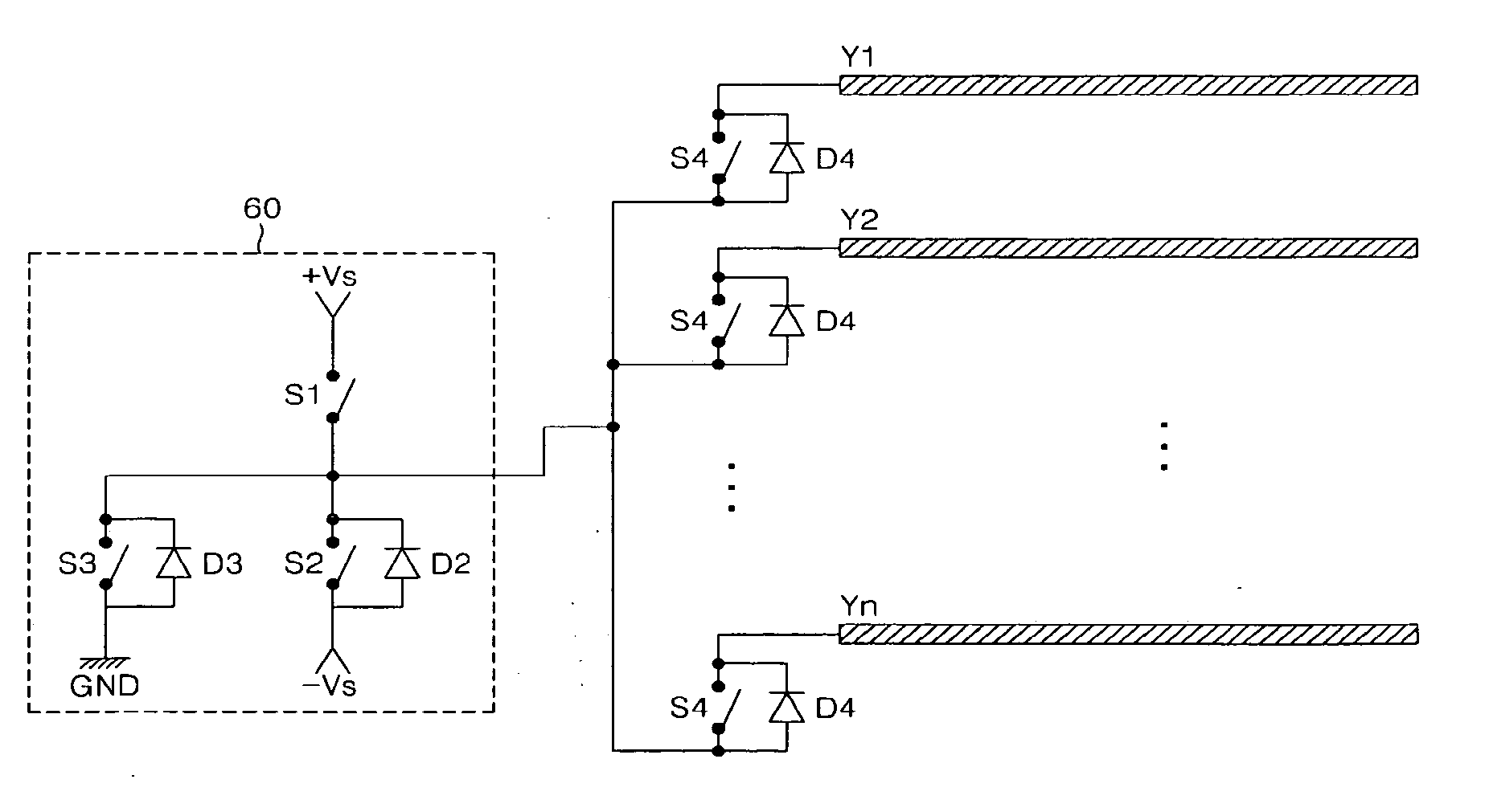
The present invention provides an apparatus and method for driving a plasma display panel (PDP) that can minimize electromagnetic interference and improve stability. The apparatus includes a scan driving unit that alternately supplies sustain pulses of positive and negative polarity to the scan electrodes during a sustain period. The sustain electrodes are always connected to a ground voltage source, which prevents introduction of external noise and minimizes generation of EMI. The method includes the steps of alternately supplying sustain pulses and a ground voltage to the scan electrodes during a sub-field period. The technical effects of the invention include minimization of electromagnetic interference, improved stability of the PDP, and prevention of additional noise.

Problems solved by technology

Accordingly, there is a problem in that high EMI is generated.
Furthermore, in the prior art, since lots of switching means (i.e., line is long) are needed in order for the scan electrodes Y and the sustain electrodes Z to be connected to the ground voltage GND, there is a problem in that additional noise is generated.
In the prior art, however, since a variety of driving waveforms are supplied to the scan electrodes Y and the sustain electrodes Z, it is difficult to secure the stability of a PDP.
As a result, there are problems in that the manufacture cost is increased, leakage current is generated, etc.

Method used


Image

  • Driving method for plasma display panel
  • Driving method for plasma display panel
  • Driving method for plasma display panel

Examples


Embodiment Construction

[0046] Preferred embodiments of the present invention will be described in more detail with reference to the drawings.

[0047]FIG. 5 is a block diagram showing an apparatus for driving a PDP according to an embodiment of the present invention.

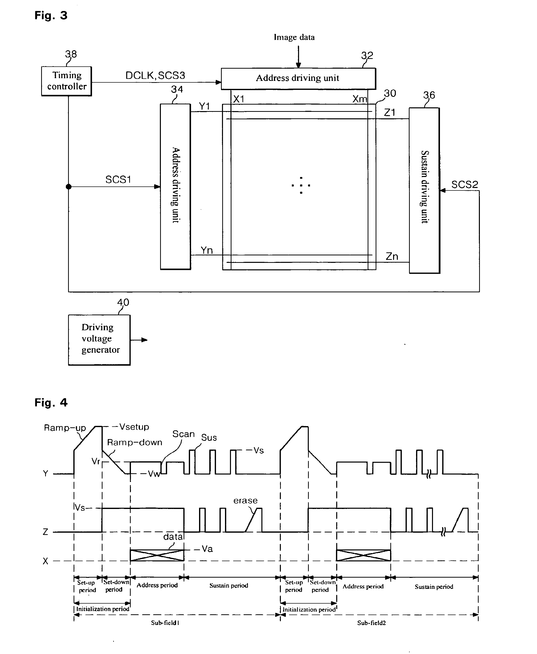
[0048] Referring to FIG. 5, the apparatus for driving the PDP according to an embodiment of the present invention includes a address driving unit 52 for driving address electrodes X1 to Xm disposed in a panel 50, a scan driving unit 54 for driving scan electrodes Y1 to Yn disposed in the panel 50, a driving voltage generator 58 for applying a driving voltage to the driving units 52, 54, and a timing controller 56 for applying control signals SCS1, SCS2 to the driving units 52, 54. At this time, sustain electrodes Z1 to Zn (omitted) disposed in the panel 50 are connected to a ground voltage GND.

[0049] The driving voltage generator 58 generates a variety of driving voltages, and supplies the generated voltages to the address driving unit 52 and ...


PUM


Abstract

Disclosed herein is an apparatus and method for driving a plasma display panel, wherein electromagnetic interference is minimized and stability is improved. According to the present invention, the apparatus for driving a PDP includes a plurality of scan electrodes and sustain electrodes, which are formed parallel to each other, and a scan driving unit for alternately supplying sustain pulses of the positive polarity and the negative polarity to the scan electrodes during a sustain period, wherein the sustain electrodes are connected to a ground voltage source, and thus always keep a ground voltage.

Description

CROSS-REFERENCES TO RELATED APPLICATIONS [0001] This Nonprovisional application claims priority under 35 U.S.C. § 119(a) on Patent Application No. 10-2004-0015057 filed in Korea on Mar. 5, 2004, the entire contents of which are hereby incorporated by reference. FIELD OF THE INVENTION [0002] The present invention relates to an apparatus and method for driving a plasma display panel, and more particularly, to an apparatus and method for driving a plasma display panel, wherein electromagnetic interference is minimized and stability is improved. BACKGROUND OF THE RELATED ART [0003] A plasma display panel (hereinafter, referred to as a ‘PDP’) is adapted to display an image including characters or graphics by light-emitting phosphors with ultraviolet of 147 nm generated during the discharge of a gas such as He+Xe, Ne+Xe or He+Ne+Xe. This PDP can be easily made thin and large, and it can provide greatly increased image quality with the recent development of the relevant technology. Particu...

Claims


Application Information

Patent Timeline
Patent Type & Authority Applications(United States)
IPC IPC(8): H04N5/66G09F9/313G09G3/20G09G3/288G09G3/294G09G3/296H01J17/49
CPCG09G3/288G09G3/294G09G3/2946G09G2330/06G09G2310/06G09G2320/0228G09G2320/043G09G3/296B61B1/02E01F1/00E04F11/1804E04F11/1808F16B5/02
Inventor MOON, SEONG-HAK
Owner LG ELECTRONICS INC
Learn More