Live cell chamber for microscopes

a live cell chamber and microscope technology, applied in the field of specimen mounts for microscopes, can solve the problems of frequent leakage of liquid within the chamber, frequent damage to the glass plate, and incomplete coupling between the glass plate and the chamber body, so as to simplify the construction of the live cell chamber, facilitate and rapid mounting of specimens, and reduce the number of components

Inactive Publication Date: 2005-09-08
LEE YONGJIN
View PDF4 Cites 28 Cited by
  • Summary
  • Abstract
  • Description
  • Claims
  • Application Information

AI Technical Summary

Benefits of technology

[0011] The present invention has been made to solve the above problems, and it is an object of the present invention to provide a live cell chamber for microscopes, designed to have a reduced number of components, allow some components to be coupled to each other through magnetic force, and to provide a chamber body having a closable upper portion in order to allow a survival environment of a specimen to be created only within the chamber, thereby simplifying the construction of the live cell chamber, allowing easy and rapid mounting of a specimen therein, and reducing operating costs of the live cell chamber.

Problems solved by technology

As such, the conventional hook-type or screw type live cell chamber is adapted to allow the glass plate to be coupled to the chamber body through the hook or screw structure, so that over pressure or vibration arising upon coupling of the hooks or the screw result in frequent damage to the glass plate and incomplete coupling between the glass plate and the chamber body, thereby causing frequent leakage of liquid within the chamber.
Furthermore, since the live cell chamber as described above requires a number of components for coupling, and has a complicated construction, these chambers are not only difficult to operate, but also require extensive times for mounting the specimen, thereby critically influencing survival of the specimen and experimental environment.
Additionally, since the specimen is observed with an upper portion of the chamber being opened, it is necessary to input excess amount of mixture of gases into the chamber in order to satisfy the experimental requirements for survival of the specimen, thereby significantly increasing operating costs of the live cell chamber.

Method used


Image

  • Live cell chamber for microscopes
  • Live cell chamber for microscopes
  • Live cell chamber for microscopes

Examples


Embodiment Construction

[0019] Preferred embodiments will now be described in detail with reference to the accompanying drawings.

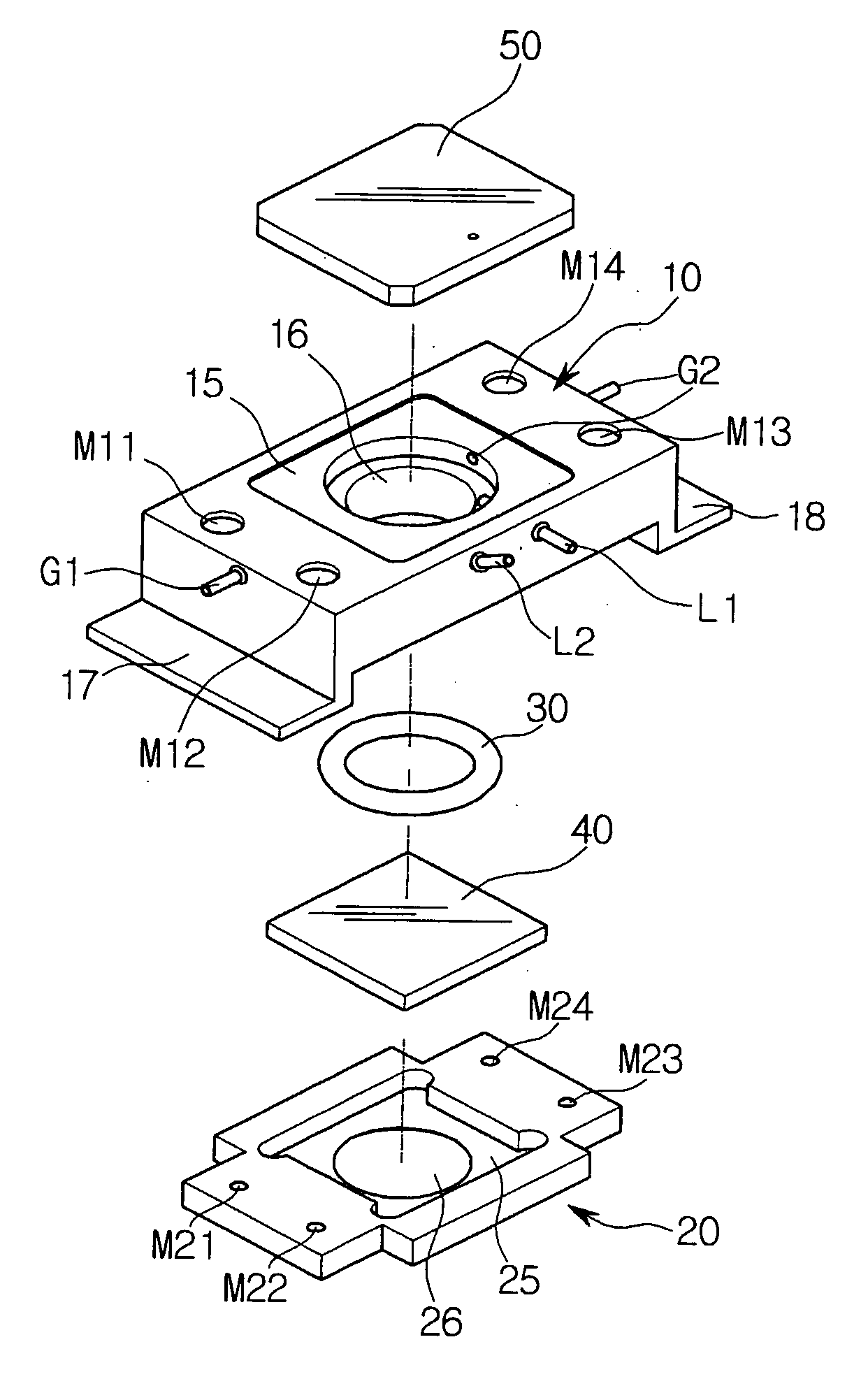
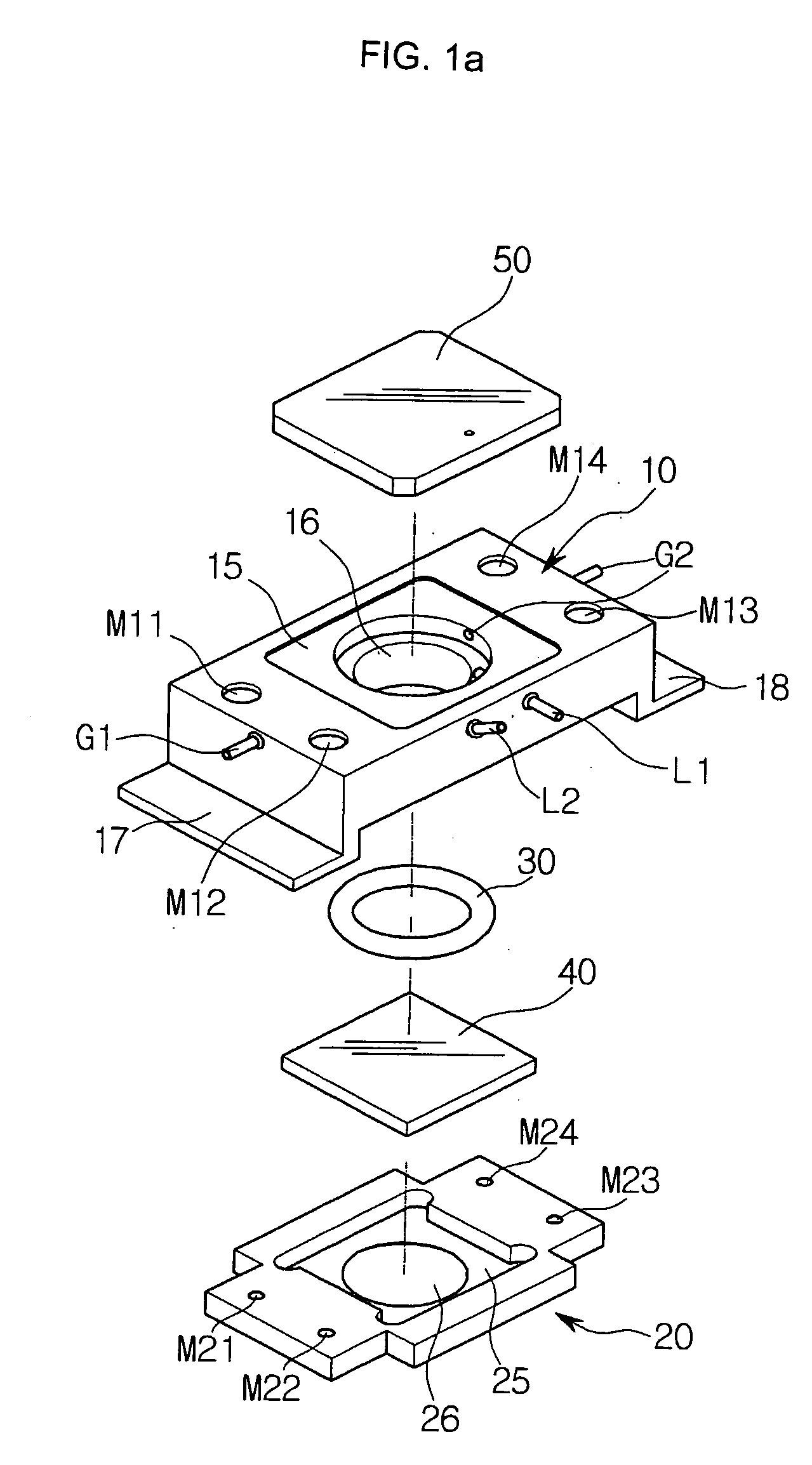
[0020]FIG. 1a is an exploded front perspective view of a live cell chamber according to the present invention. Referring to FIG. 1a, the live cell chamber comprises a chamber body 10, a specimen mounting base 20, an O-ring 30, a specimen glass 40, a transparent cover 50, and the like.

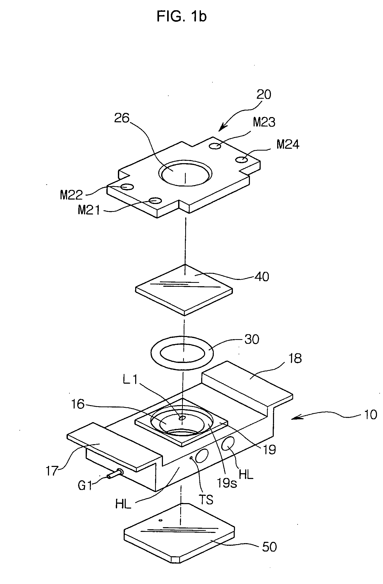
[0021] The chamber body 10 has a parallelepiped shape, and a vertically perforated cylindrical inner space 16 defined therein. A cover mounting portion 15 having a stepped planar surface is formed at one end of the inner space 16 such that the transparent cover 50 can be seated thereon. The height of the cover mounting portion 15 may be the same as the thickness of the transparent cover 50, so that, when the transparent cover 50 is seated on the cover mounting portion 15, the top surface of the transparent cover 50 may be coplanar with the top surface of the chamber body 10.

[0022] The chamber body...


PUM

PropertyMeasurementUnit
transparentaaaaaaaaaa
temperatureaaaaaaaaaa
elasticaaaaaaaaaa

Abstract

Disclosed herein is a live cell chamber for a microscope. The live cell chamber comprises a chamber body, a transparent specimen plate, a specimen mounting base, and at least one sealing member. The chamber body includes at least one vertically perforated inner space, and a plurality of magnets. The specimen mounting base includes a specimen receiving portion, a magnetic member embedded around the specimen receiving portion such that the magnetic member can react to the magnets, and at least one through hole formed through the specimen receiving portion such that the center of the through hole is collinear with the center of the inner space of the chamber body. The sealing member is attached to the one end of the inner space while being attached at the other side to an upper surface of the specimen plate, thereby sealing a space defined between the inner space and the plate.

Description

CLAIMING FOREIGN PRIORITY [0001] The applicant claims and requests a foreign priority, through the Paris Convention for the Protection of Industry Property, based on a patent application filed in the Republic of Korea (South Korea) with the filing date of Mar. 6, 2004, with the patent application number 10-2004-0015271, by the applicant. (See the Attached Declaration). BACKGROUND OF THE INVENTION [0002] 1. Field of the Invention [0003] The present invention relates to a specimen mount for microscopes, and, more particularly, to a live cell chamber for microscopes. [0004] 2. Description of the Related Art [0005] A microscope generally comprises an ocular lens, a body tube, a revolving nosepiece, an objective lens, a macroscrew, a microscrew, a stand, a stage, a reflector, and the like. [0006] In order to observe a certain specimen using a microscope, the specimen must be located on the stage of the microscope. In this way, for a specimen of dead cells, the specimen is attached to a g...

Claims


Application Information

Patent Timeline
Patent Type & Authority Applications(United States)
IPC IPC(8): G02B21/26C12M1/22
CPCB01L2200/025B01L2200/0689B01L2200/147B01L2300/041G02B21/34B01L2300/0822B01L2300/0877B01L2300/088B01L2300/18B01L2300/0654A62B1/14A62B1/18
Inventor LEE, YONGJIN
Owner LEE YONGJIN
Why Eureka
Try Eureka