Shoulder prosthesis

a shoulder joint and humeral technology, applied in the field of shoulder joint prosthesis, can solve the problem of not being able to achieve all of the natural range of motion of a healthy shoulder joint, and achieve the effect of great flexibility

Active Publication Date: 2005-09-08
BIOMET MFG CORP
View PDF73 Cites 93 Cited by
  • Summary
  • Abstract
  • Description
  • Claims
  • Application Information

AI Technical Summary

Benefits of technology

[0008] In a first preferred embodiment, a humeral component for a total shoulder prosthesis is provided for adjustable radial offset of the head with respect to the stem. The present invention includes an adapter interposed between a stem and a head. The adapter is eccentrically coupled to the stem such that relative angular positioning of the adapter on the stem will effect a first adjustment in the radial offset. Likewise, the head component is eccentrically coupled to the adapter as such that relative angular position of the head on the adapter will effect a second radial offset adjustment. By selectively positioning the adapter and the head component with respect to the stem, an infinite adjustment of the radial offset within a given range may be achieved. As presently preferred, indicia are provided at the interface between the adapter and the head to indicate the offset vector (i.e., offset amount and direction).
[0009] In a second preferred embodiment, a humeral component for a total shoulder prosthesis is provided for adjustable angular inclination of the head component relative to the stem component. The present invention includes an adapter interposed between a stem and a head. The adapter is coupled to the stem in a first angled or non-orthogonal orientation such that relative rotatio...

Problems solved by technology

With unitary shoulder prosthesis, each design represents a compromise that is unable to achieve all of the ...

Method used


Image

  • Shoulder prosthesis
  • Shoulder prosthesis
  • Shoulder prosthesis

Examples


Embodiment Construction

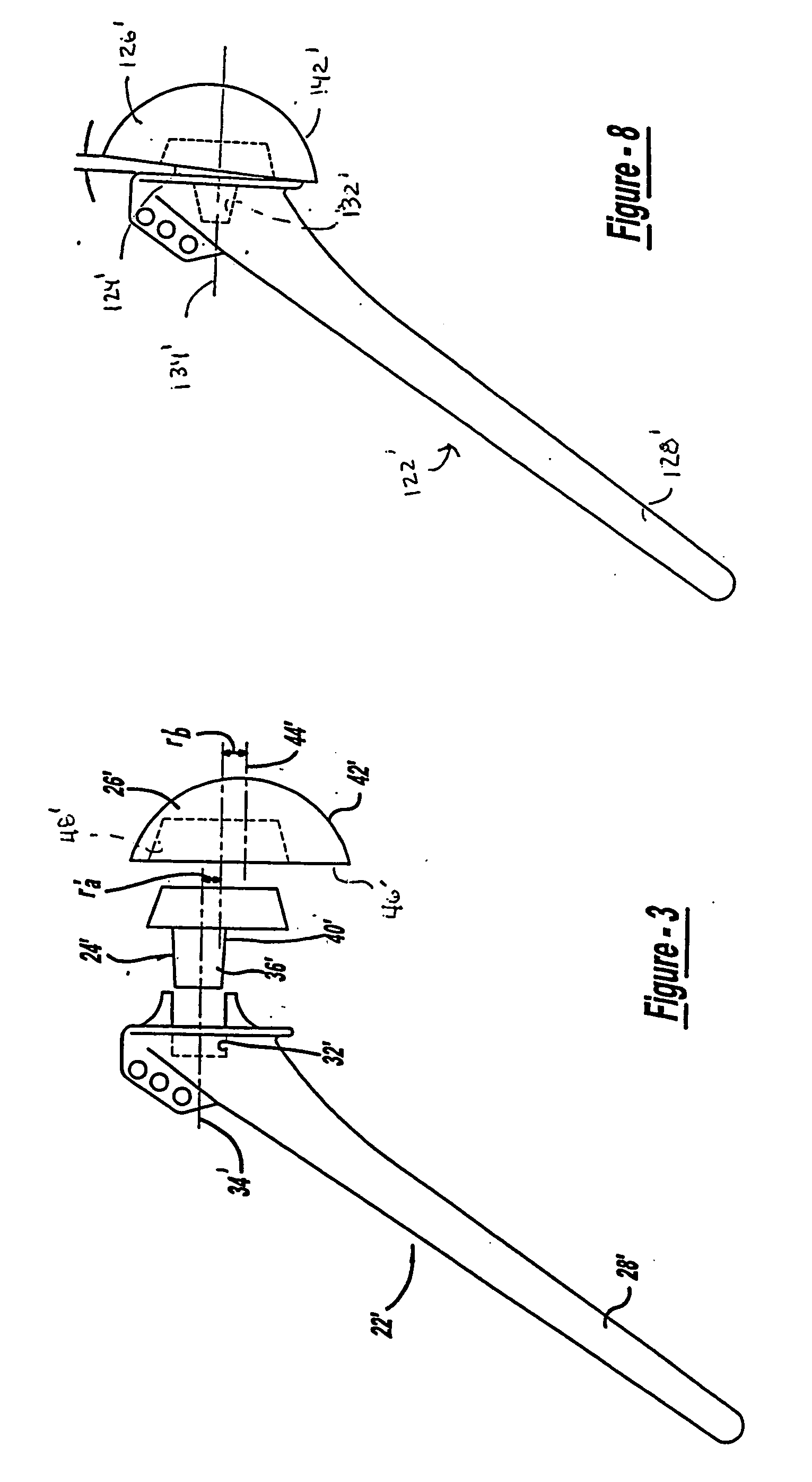
[0027] The following description of the preferred embodiments disclosing a modular joint prosthesis system which provides adjustment of the radial offset and / or angular inclination of the head relative to the stem are merely exemplary and are not intended to limit the invention or its application or uses. Moreover, while the present invention is described in detail, generally with respect to a shoulder joint prosthesis system, it will be appreciated by those skilled in the art that the present invention is not limited to the preferred embodiments illustrated herein.

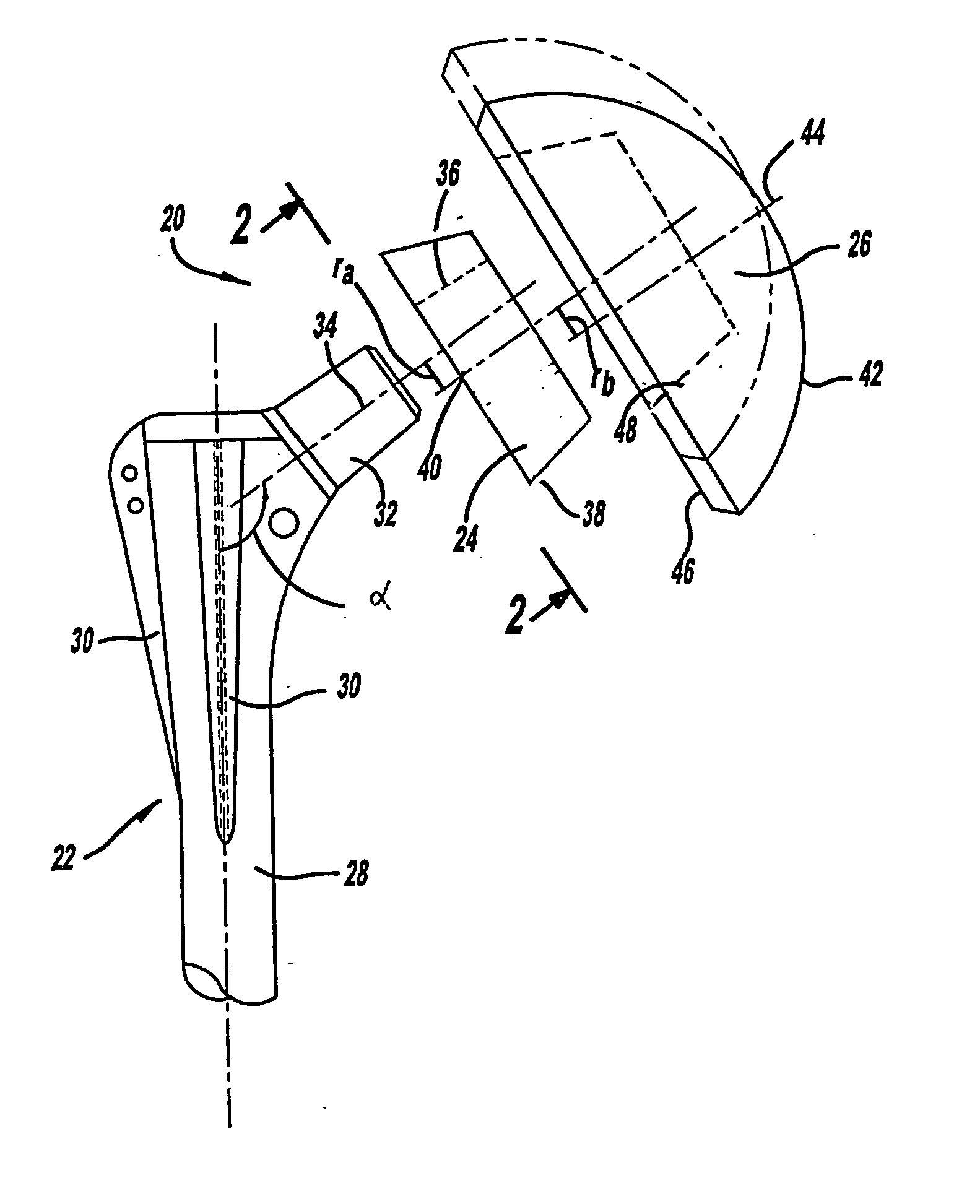
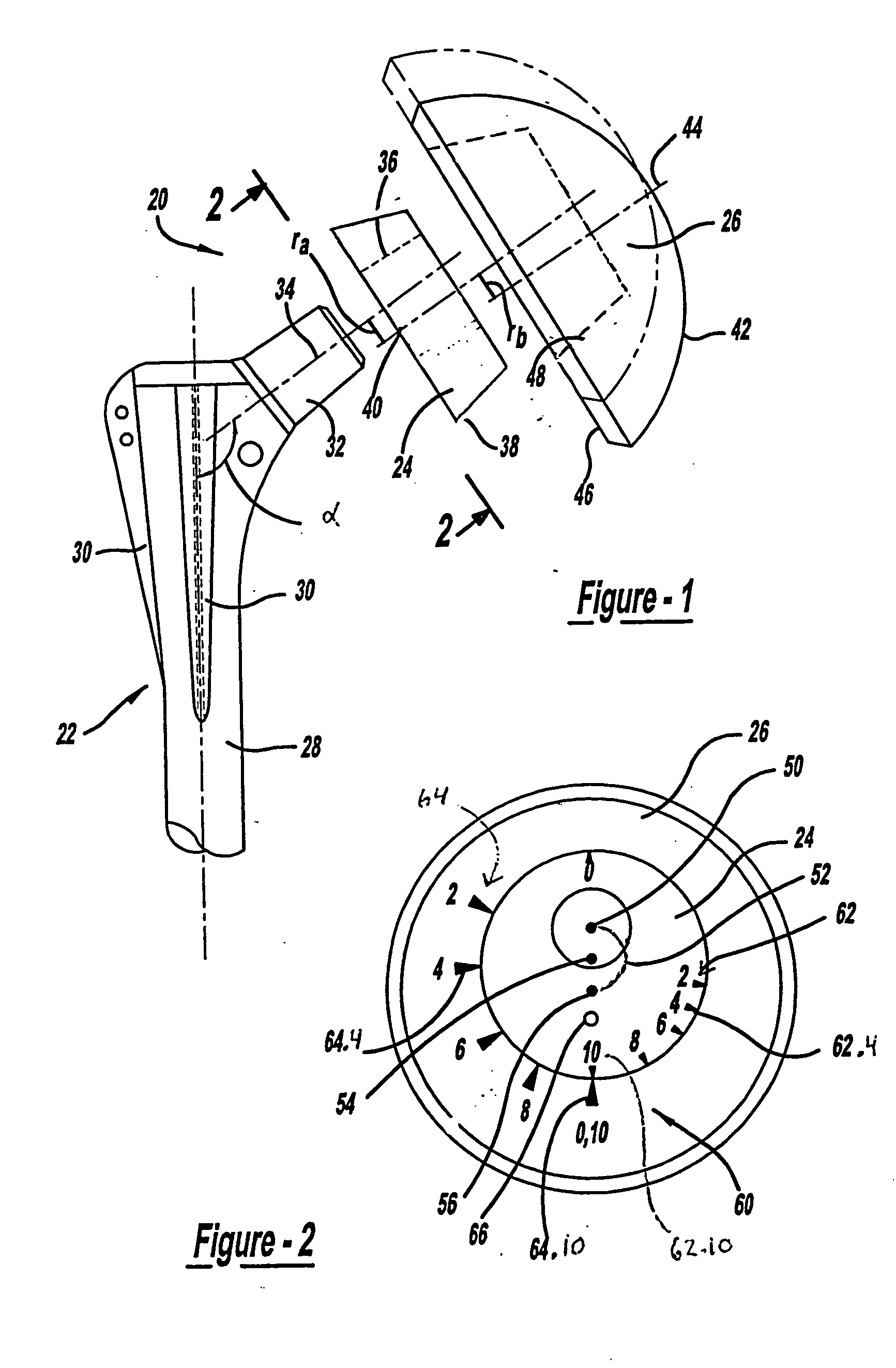
[0028] With reference now to FIG. 1, shoulder prosthesis 20 in accordance with the present invention is illustrated to include a stem 22, an adapter 24 and a head 26. Stem 22 includes a rod portion 28 adapted to be received in the medullary canal of the humerus. A plurality of fins 30 are formed near the upper end of rod 28 for locating and fixing the stem within a humerus. A male taper 32 extends obtusely from rod 28 to...


PUM


Abstract

The present invention is directed to a modular shoulder prosthesis having an adjustable radial offset and/or angular inclination provided by relative rotation of an adapter interdisposed between the stem and the head. Specifically, the interface configuration between the stem and the adapter, as well as between the adapter and the head are designed such that relative positioning of these components provides a continuous adjustment in the radial offset and/or angular inclination. Indicia are provided at the interface between the adapter and the head to precisely determine the magnitude and direction of the adjustment being made.

Description

CROSS-REFERENCE TO RELATED APPLICATIONS [0001] This application is a divisional of U.S. patent application Ser. No. 10 / 192,787, filed on Jul. 10, 2002, which claims the benefit of U.S. Provisional Application No. 60 / 304,651, filed Jul. 11, 2001. The disclosures of the above applications are incorporated herein by reference.BACKGROUND OF THE INVENTION [0002] The present invention relates to a prosthesis for replacing and reconstructing a portion of the humerus and more specifically to a modular humeral prosthesis which allows for total shoulder joint replacement. [0003] The shoulder joint is considered to be one of the most complex joints in the body. The scapula, the clavicle and the humerus all meet at the shoulder joint. The head of the humerus fits into a shallow socket of the scapula called the glenoid fossa to form a mobile joint. When the joint is articulated, the humeral head moves in the glenoid fossa to provide a wide range of motion. The shoulder joint may suffer from vari...

Claims


Application Information

Patent Timeline
IPC IPC(8): A61F2/00A61F2/02A61F2/30A61F2/40A61F2/46
CPCA61F2/40A61F2002/30887A61F2/4059A61F2002/30329A61F2002/30332A61F2002/30341A61F2002/30344A61F2002/30354A61F2002/30378A61F2002/3038A61F2002/30484A61F2002/30507A61F2002/30515A61F2002/30537A61F2002/30538A61F2002/30542A61F2002/30589A61F2002/30604A61F2002/30616A61F2002/30617A61F2002/30714A61F2002/30774A61F2002/30795A61F2002/30884A61F2002/30902A61F2002/4018A61F2002/4029A61F2002/4037A61F2002/4044A61F2002/4062A61F2002/4629A61F2002/4641A61F2220/0025A61F2220/0033A61F2250/0004A61F2250/0006A61F2250/0089A61F2250/0097A61F2/4014A61F2002/30331A61F2002/30339A61F2002/3054A61F2002/3071A61F2/30A61F2/32A61F2/3609A61F2002/30886A61F2002/4033
Inventor STONE, KEVIN T.CORDARO, NICHOLAS MICHAEL
Owner BIOMET MFG CORP
Why Eureka
Try Eureka