Valve train lubricating structure in internal combustion engine

a technology of internal combustion engine and lubricating structure, which is applied in the direction of engine revolution, lubrication of auxillaries, lubrication check valves, etc., can solve the problems of not considering a structural feature of the lubricating structure, and not ensuring a sufficient amount of lubricating oil in the valve train. , to achieve the effect of reducing the supply pressur

Inactive Publication Date: 2005-09-15
HONDA MOTOR CO LTD
View PDF7 Cites 8 Cited by
  • Summary
  • Abstract
  • Description
  • Claims
  • Application Information

AI Technical Summary

Benefits of technology

[0012] Under these circumstances, there is a need for the improved lubricating structure incorporating the following specific viewpoints. More specifically, the improved lubricating structure prevents a drop in pressure of the supply oil in the supply of the lubricating oil to the valve train including the camshaft or the like. The improved structure ensures a sufficient amount of supply of the lubricating oil to the valve train including the camshaft or the like particularly when the internal combustion engine runs at low speed. The improved structure achieves positive and effective lubrication in the valve train. Further, the improved structure is intended for simple and low-cost lubrication. The improved structure particularly represents a viewpoint of an improved disposition of the supply path of the lubricating oil.
[0014] According to the present invention, the valve train lubricating structure in the internal combustion engine includes an oil pump, a supply path, and a plurality of branch supply paths. The oil pump is rotated by being operatively connected with the rotation of a crankshaft. The supply path provides a route, through which the lubricating oil delivered from the oil pump is supplied to an oil gallery. The plurality of branch supply paths provides routes, through which the lubricating oil is supplied to different parts of the internal combustion engine. One of the plurality of branch supply paths forms a supply path for the lubricating oil to the valve train. The supply path for the lubricating oil to the valve train includes a check valve and the supply path going to the oil gallery is branched off at a point upstream of the check valve. Because of this arrangement, a drop in the supply pressure can be suppressed and a sufficient amount of supply of the lubricating oil to the valve train can be ensured. Further, positive and effective lubrication of the camshaft and the valve train including the camshaft can be achieved.

Problems solved by technology

When this phenomenon occurs, a sufficient amount of lubricating oil is not secured for the valve train.
Hei 6-18007 does not, however, ensure a sufficient amount of supply of the lubricating oil in the valve train.
Further, no consideration is given to a structural feature of the lubricating structure in terms of securing a sufficient amount of the lubricating oil to be supplied to the valve train by preventing a drop in the supply pressure of the lubricating oil to the valve train.

Method used


Image

  • Valve train lubricating structure in internal combustion engine
  • Valve train lubricating structure in internal combustion engine
  • Valve train lubricating structure in internal combustion engine

Examples


Embodiment Construction

0F THE PREFERRED EMBODIMENTS

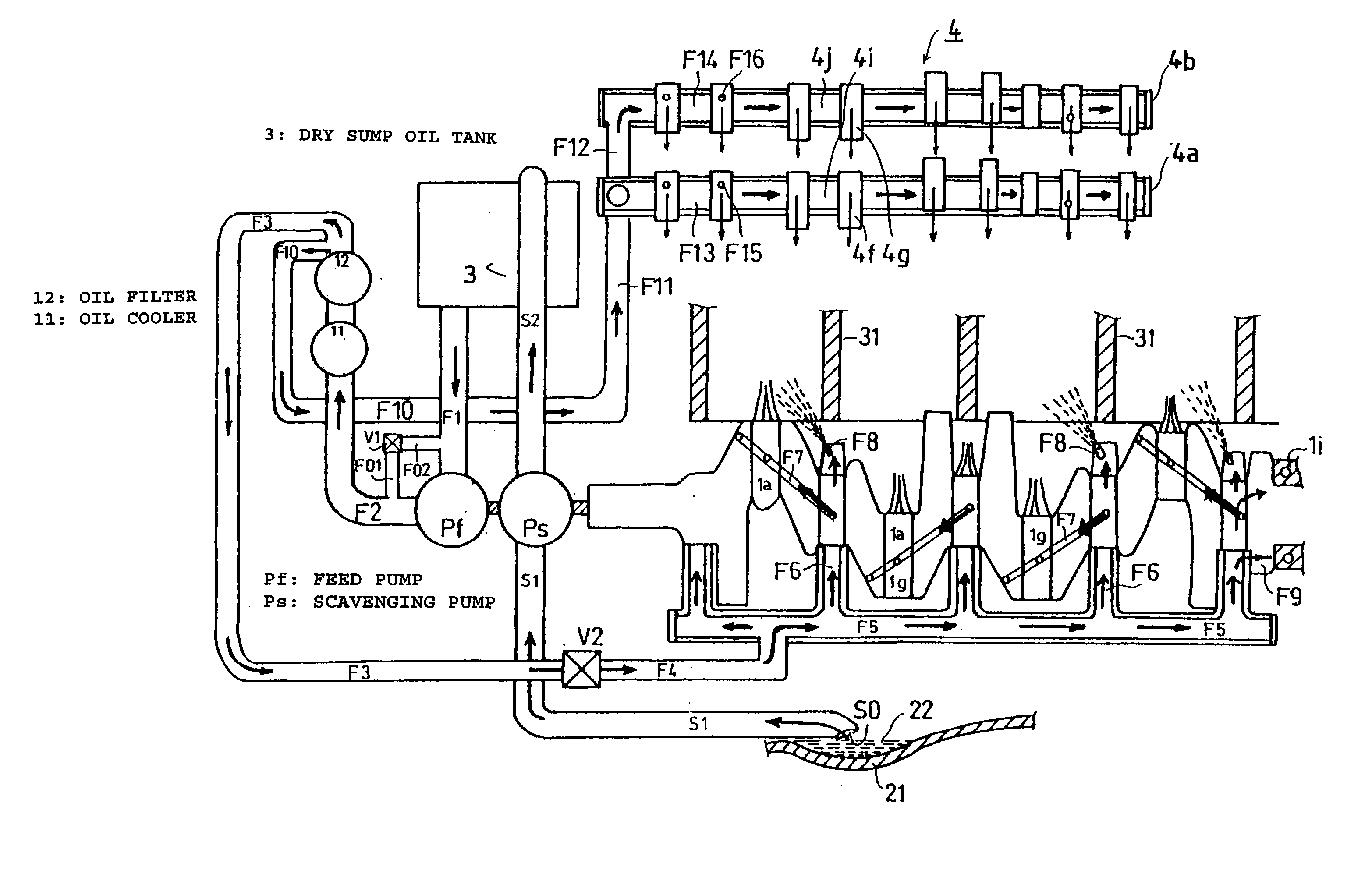
[0030] The present invention is embodied by providing a lubricating oil supply path for the exclusive use for a valve train, through which the lubricating oil is supplied directly to a camshaft or the like without letting the lubricating oil flow via an oil gallery.

[0031] A preferred embodiment of the present invention will be described with reference to FIGS. 1 through 12.

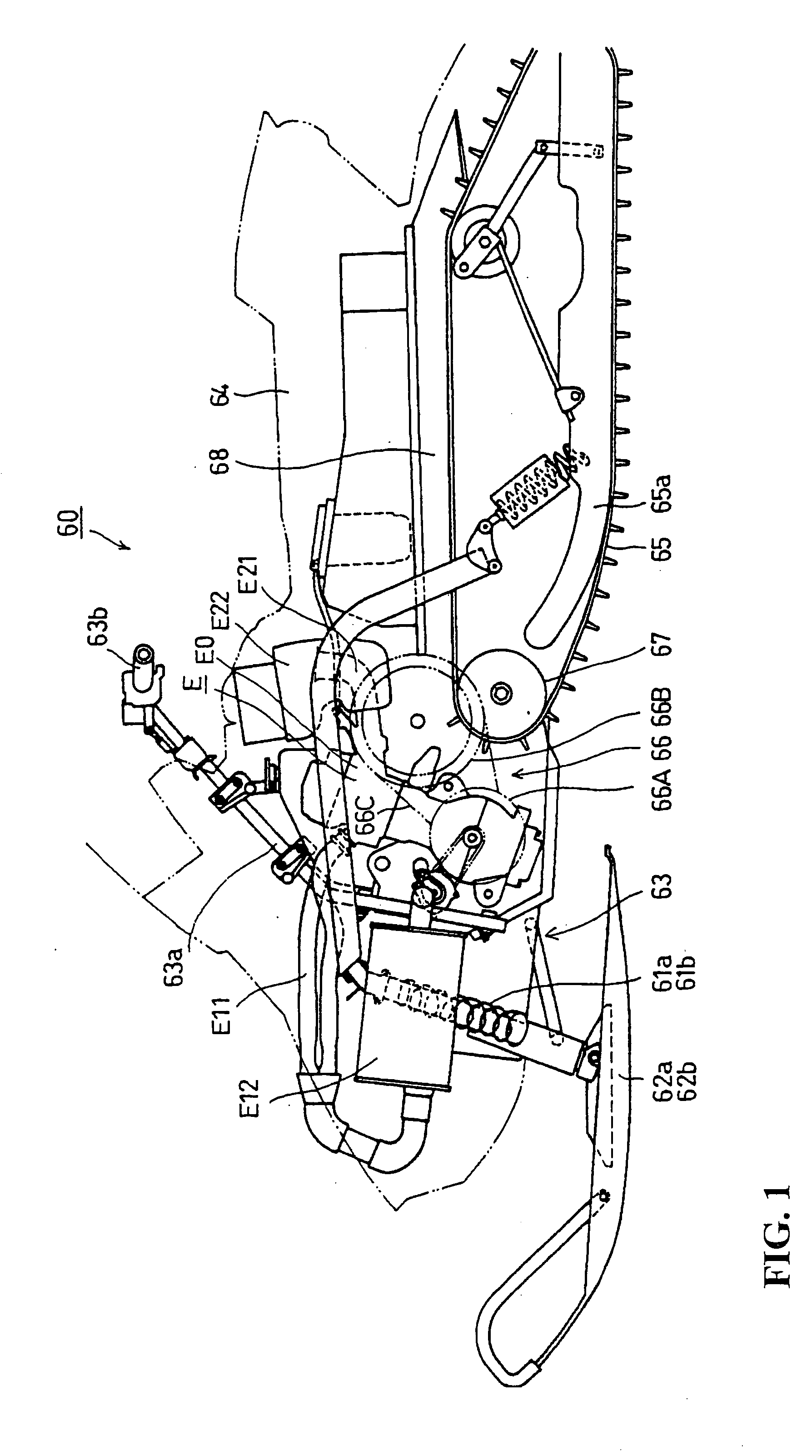
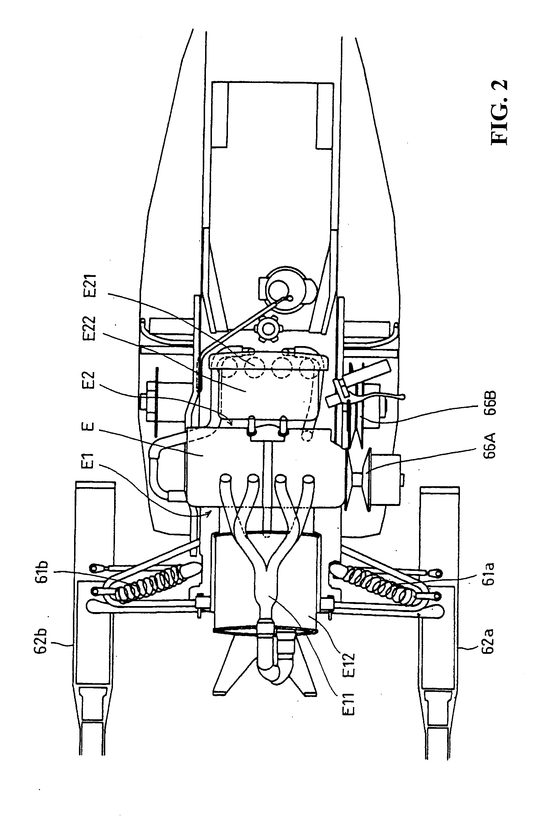
[0032]FIG. 1 is a general side elevational view showing a snow vehicle 60 in which an internal combustion engine E according to the present invention is mounted. FIG. 2 is a general top view showing the snow vehicle 60. As can be understood from FIGS. 1 and 2, the internal combustion engine E is mounted at a location nearer a front side of a vehicle body of the snow vehicle 60. Right and left front suspensions 61a, 61b are provided at a front portion of the vehicle body. Steering control skis 62a, 62b are connected to the front suspensions 61a, 61b, respectively.

[0033] The steering c...


PUM


Abstract

To prevent a drop in a lubricating oil supply pressure in a valve train from occurring by disposing a lubricating oil supply path for the exclusive use of the valve train without allowing the lubricating oil to flow through an oil gallery, thereby securing a sufficient amount of supply of the lubricating oil in the valve train to enhance lubrication efficiency. A feed pump rotating with a crankshaft is disposed at a leftward end of the crankshaft. Lubricating oil supplied from the feed pump flows through an oil cooler and an oil filter. Part of the lubricating oil is supplied through a lubricating oil supply path to an oil gallery and to journals, crankpins, and the like of the crankshaft. The other part of the lubricating oil is supplied through lubricating oil supply paths for the exclusive use of the valve train.

Description

CROSS-REFERENCE TO RELATED APPLICATIONS [0001] The present application claims priority under 35 USC 119 to Japanese Patent Application No. 2004-068158 filed on Mar. 10, 2004 the entire contents of which are hereby incorporated by reference. BACKGROUND 0F THE INVENTION [0002] 1. Field of the Invention [0003] The present invention relates generally to a structure of an internal combustion engine. More particularly, to a lubricating structure for a valve train including a camshaft or the like in an internal combustion engine. [0004] 2. Description of Background Art [0005] One of the most commonly used conventional lubricating structures for a valve train such as a camshaft or the like in an internal combustion engine is constructed as follows. More specifically, lubricating oil pumped up from an oil strainer by an oil pump flows past an oil filter as the oil is fed from the oil pump through a lubricating oil inflow path. The lubricating oil is thereby fed to an oil gallery. The lubrica...

Claims


Application Information

Patent Timeline
Patent Type & Authority Applications(United States)
IPC IPC(8): F01M1/06F01M1/02F01M9/10F01M11/02F16N23/00
CPCF01M1/06F01M1/16F01M2250/64F01M2001/126F01M9/10
Inventor HOI, YOSUKE
Owner HONDA MOTOR CO LTD
Why Eureka
Try Eureka