Automatic braking light

a technology of automatic braking and stop light, which is applied in the direction of basic electric elements, electric devices, transportation and packaging, etc., can solve the problems of many pedal cyclists being injured or killed in traffic accidents, erratic and it is difficult to predict the acceleration and deceleration of a cyclis

Inactive Publication Date: 2005-09-15
BRACKEN GERALD
View PDF6 Cites 4 Cited by
  • Summary
  • Abstract
  • Description
  • Claims
  • Application Information

AI Technical Summary

Benefits of technology

[0004] The present invention seeks to provide an automatic braking light that can be fixed to pedal cycles and other vehicles and is inertia-activated on deceleration. In a preferred embodiment, the braking light includes a case in which a battery in a holder swings overhead a pivot / axle from a stop where it is at rest forward to a resilient spring means which absorbs the deceleration force and simultaneously closes an electric circuit to a display of light emitting diodes to thereby provide a warning to other road users of the deceleration.

Problems solved by technology

Many pedal cyclists suffer injuries or death in traffic accidents every year.
One reason for this is that acceleration and deceleration of a cyclist is erratic when compared to motor powered vehicles as it is influenced by factors such as incline of the road, the gear being used and the level of fatigue of the cyclist.
As it is very difficult to predict acceleration and deceleration of a cyclist, other road users try to pass them by with a wider berth than they would typically give other road users.
However, where a cyclist decelerates suddenly without warning and is in the path of another road user, it is sometimes too late to react properly by the time the other road user has realized the cyclist is / has decelerated.

Method used


Image

  • Automatic braking light
  • Automatic braking light
  • Automatic braking light

Examples


Embodiment Construction

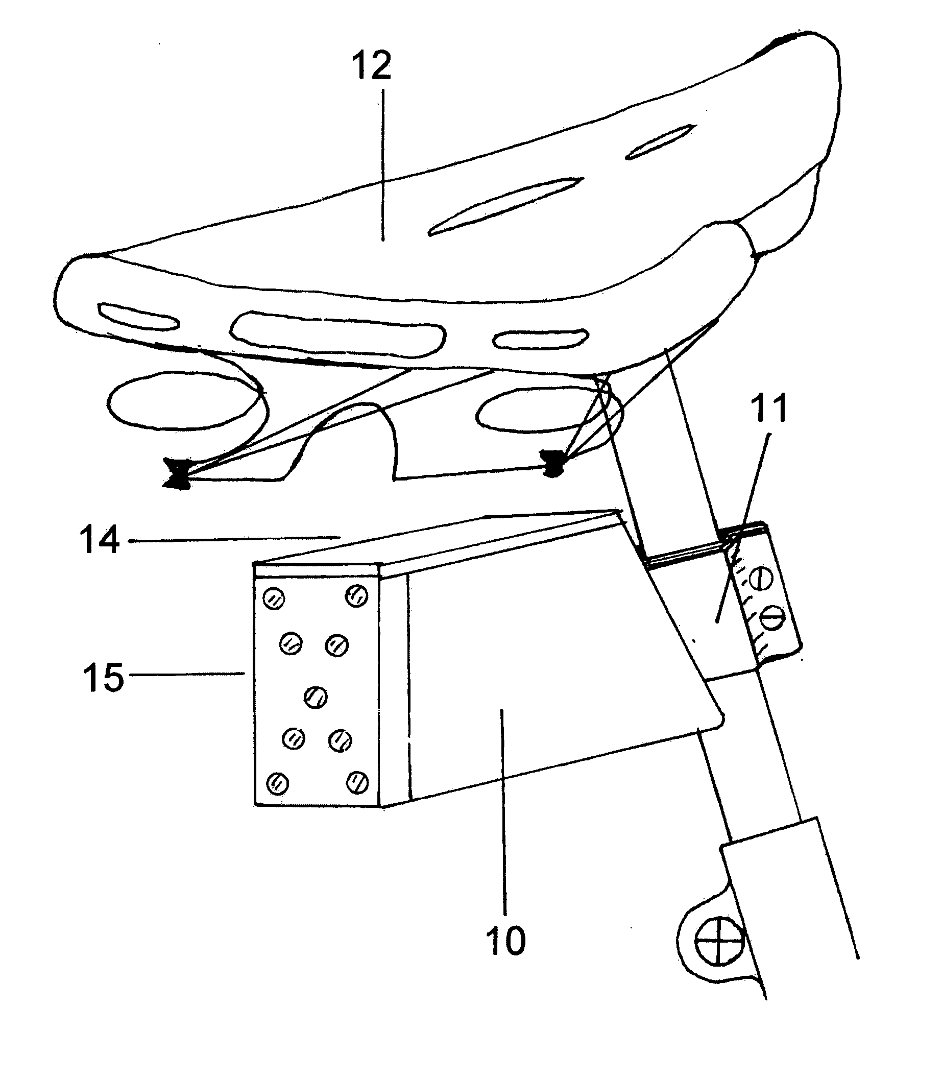
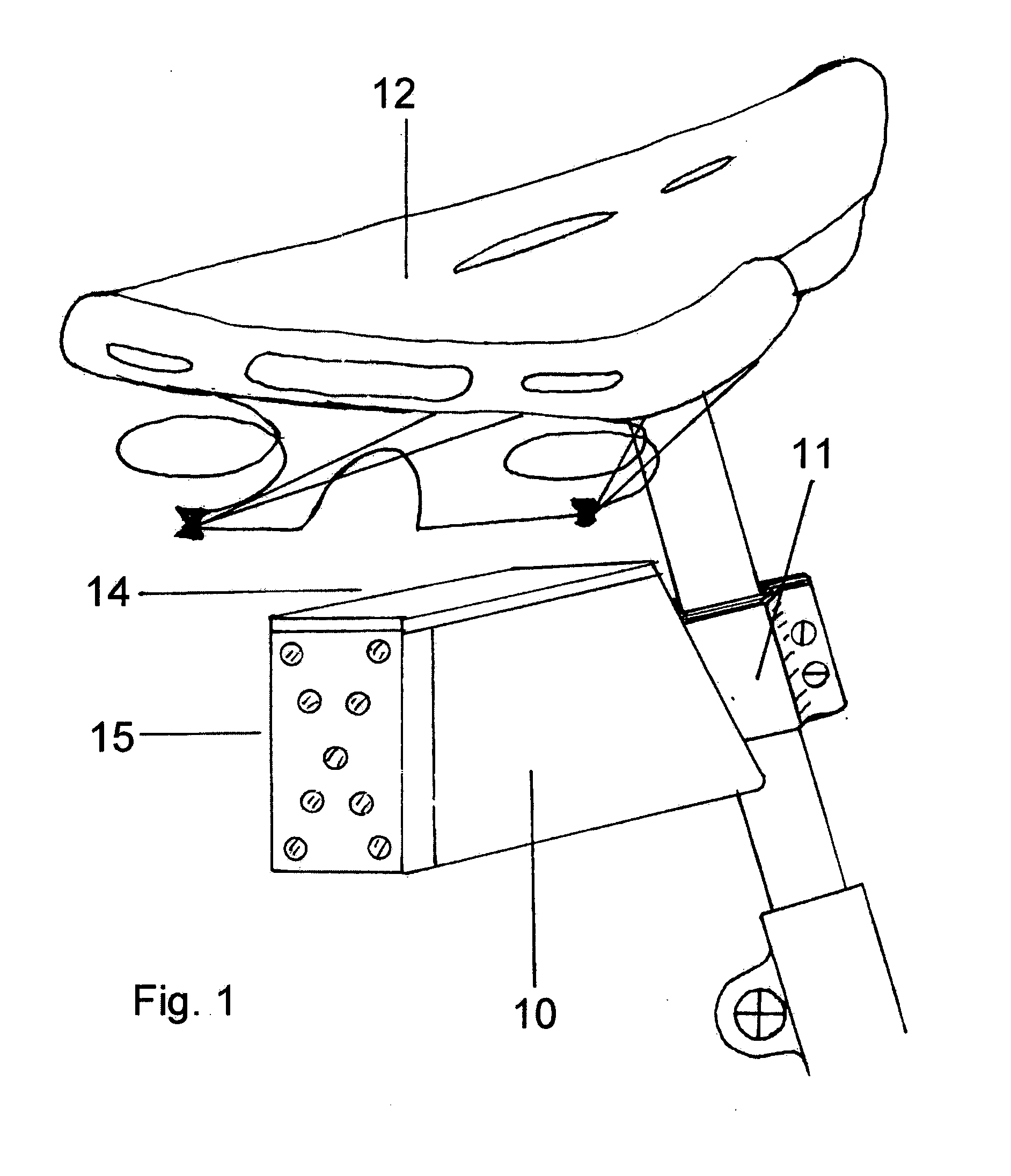
[0018]FIG. 1 shows, in perspective, a braking light according to an embodiment of the present invention fitted to a cycle frame. The braking light unit includes a compact case 10 secured to the cycle frame 2 under the saddle 12 by a rigid attachment bracket 11 which maintains the angle of operation of the components of the unit Access for battery replacement is via a lid 14 on top of the case 10. A nine LED display 15 projects to the rear.

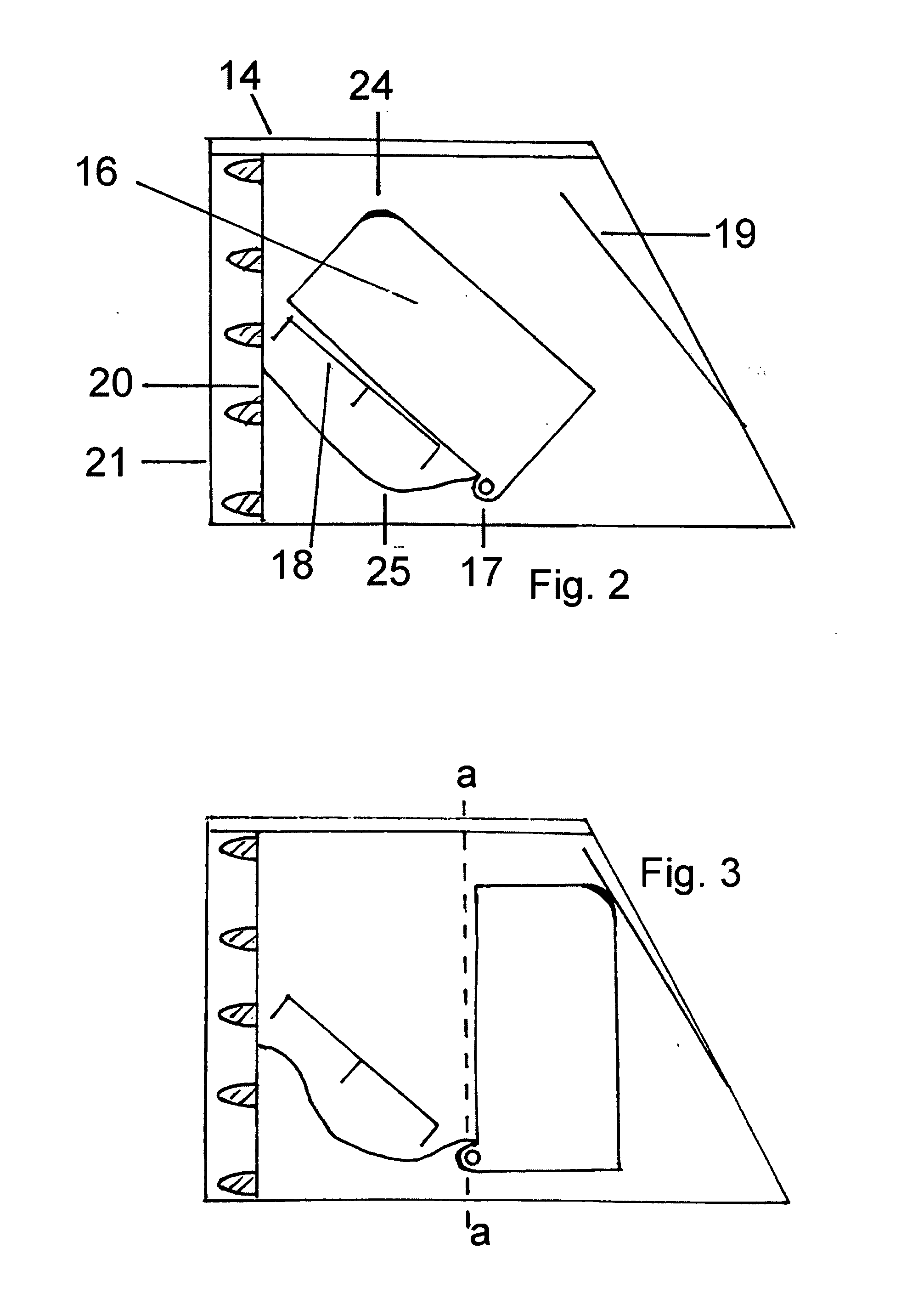
[0019]FIG. 2 is a sectional view of the braking light of FIG. 1 in an “off” position and FIG. 3 is a sectional view of the braking light of FIG. 1 in an “on” position. The unit 1 includes a battery holder 16 that is arranged to pivot over an offset axle 17. In the “off” position, the battery holder 16 rests on a stop 18 at an angle of approximately 42° above horizontal. The nine LED display 15 is mounted on a printed circuit board 20 fitted towards the rear of the case 10, under a translucent cover 21.

[0020] The arc of forward movement of the hol...


PUM


Abstract

An inertia-activated braking light (1) for attachment to pedal cycles and the like. A display of LEDs (15) is automatically illuminated on deceleration. This is achieved by an inertia mass closing a circuit on deceleration to provide electrical power to illuminate the light emitting diodes.

Description

FIELD OF THE INVENTION [0001] This invention relates to an automatic braking light or stop light for pedal cycles and the like and is particularly applicable for vehicles with no electric system. BACKGROUND TO THE INVENTION [0002] Many pedal cyclists suffer injuries or death in traffic accidents every year. One reason for this is that acceleration and deceleration of a cyclist is erratic when compared to motor powered vehicles as it is influenced by factors such as incline of the road, the gear being used and the level of fatigue of the cyclist. As it is very difficult to predict acceleration and deceleration of a cyclist, other road users try to pass them by with a wider berth than they would typically give other road users. However, where a cyclist decelerates suddenly without warning and is in the path of another road user, it is sometimes too late to react properly by the time the other road user has realized the cyclist is / has decelerated. STATEMENT OF INVENTION [0003] Accordin...

Claims


Application Information

Patent Timeline
Patent Type & Authority Applications(United States)
IPC IPC(8): B60Q1/44B62J6/04
CPCB62J6/04B60Q1/445B62J6/045
Inventor BRACKEN, GERALD
Owner BRACKEN GERALD
Why Eureka
Try Eureka