Vehicle brake control apparatus

Inactive Publication Date: 2005-07-26
DENSO CORP
View PDF9 Cites 43 Cited by
  • Summary
  • Abstract
  • Description
  • Claims
  • Application Information

AI Technical Summary

Benefits of technology

[0017]With this arrangement, when the driver applies manual braking on the vehicle (i.e., depresses a brake pedal based on his/her own decision) during the automatic brake operation or the warning brake operation being carried out, the braking force to be generated by the braking element is increased or boosted up to a level higher than the inherent braking force corresponding to the brake operation amount given by the driver. When the braking force is increased within the range of the estimated maximum braking force being estimated based on the road surface friction coefficient, it becomes possible to realize excellent braking response within the range of the maximum braking force. On the other hand, when the braking force is increased disregarding the estimated maximum braking force being estimated based on the road surface friction coefficient, it becomes possible realize enhanced braking in the case that a maximum braking force generable from an actual road surface is larger than the estimated maximum braking force.
[0018]In the preferred embodiment of the present invention, the braking force restricting element increas

Problems solved by technology

However, the above-described conventional vehicle automatic brake control technique is subjected to the following problems.
For example, in a condition that the automatic brake operation is started in response to detection of collision danger and almost all of the grip force o

Method used


Image

  • Vehicle brake control apparatus
  • Vehicle brake control apparatus
  • Vehicle brake control apparatus

Examples


modified embodiment 1

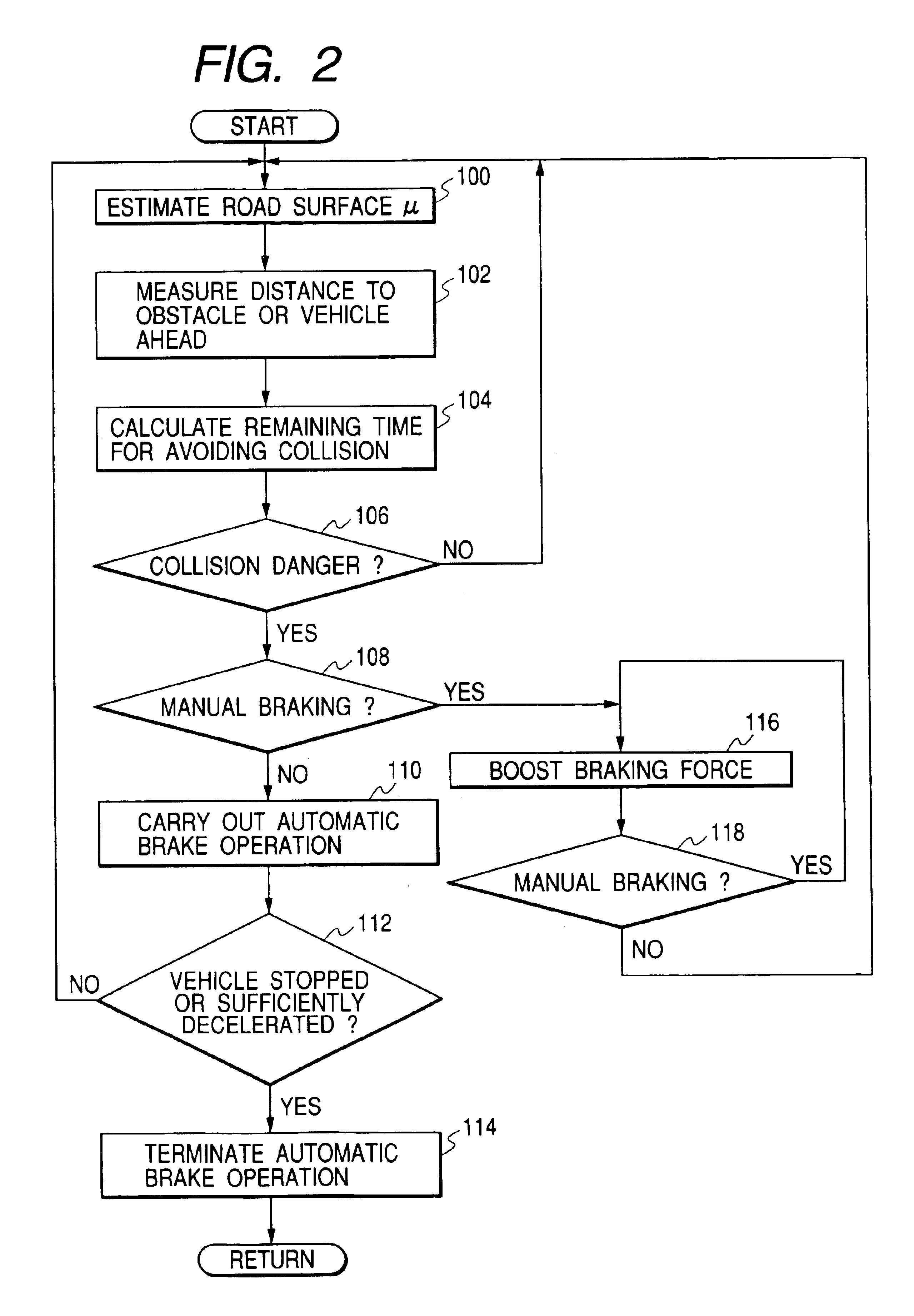
[0056]According to the above-described embodiment, when the manual braking operation is detected in the step S108, the control flow proceeds to the step S116 to increase or boost the target braking force in such a manner that a braking force value corresponding to the present manual braking operation amount is multiplied with a predetermined rate. This multiplying or boosting brake operation is restricted to somewhere in the braking force range being set in the range of the above-described estimated maximum braking force. It is however possible to increase or boost the brake pedal depression amount with a booster in response to detection of the manual braking operation, thereby generating an increased or boosted braking force which is equivalent to predetermined times the braking force to be inherently generated in response to a driver's brake operation amount during the manual braking operation while neglecting the above-described estimated maximum braking force. With this operatio...

modified embodiment 2

[0057]According to the above-described embodiment, the target braking force during the automatic brake operation is restricted to a value approximately equal to or less than a half of the generable estimated maximum braking force. The brake control technique of this invention can be used for generating a braking force as a warning given to the driver when it is judged that the possibility of collision danger is high. The braking operation for warning, i.e., the warning brake operation, is carried out periodically predetermined times.

[0058]Hereinafter, an explanation is given based on the flowchart shown in FIG. 2. According to this modified embodiment, the braking force for warning (i.e., the warning braking force) is generated at the step S110. The warning braking force is set to a value in a range corresponding to 5% to 60% of the estimated maximum braking force determined based on an estimated road surface friction coefficient μ. The warning brake operation is carried out periodi...

modified embodiment 3

[0060]In a preferred embodiment of the present invention, the braking force is for example increased to a maximum value within the range of the estimated maximum braking force, when a driver applies none of manual braking, manual steering, and manual accelerating operations within a predetermined time after the automatic brake operation or the warning brake operation is started.

[0061]This processing will be explained hereinafter with reference to a flowchart shown in FIG. 6.

[0062]When it is judged that no manual operation (i.e., no manual braking, no manual steering, and no manual accelerating operations) is performed (i.e., NO in step S108 in FIG. 2), the control flow proceeds to step S200. In the step S200, it is checked as to whether a predetermined time has elapsed or not after the automatic brake operation of step S110 is started. When the predetermined time has not elapsed yet after the automatic brake operation is started (i.e., NO in step S200), the control flow skips the fo...


PUM


Abstract

It is checked based on entered information as to whether a vehicle should be decelerated or not (S106). When the vehicle should decelerate, an automatic brake operation is carried out with a braking force being set to be smaller by a predetermined ratio than an estimated maximum braking force estimated based on a road surface friction coefficient μ(S110).

Description

BACKGROUND OF THE INVENTION[0001]This invention relates to a vehicle brake control apparatus having the capability of automatically decelerating or stopping a vehicle to avoid vehicle collision or reducing vehicle damage.[0002]The Japanese Patent Application Laid-open No. 11-348799(1999), corresponding to the U.S. Pat. No. 6,157,892, has already proposed an automatic vehicle brake control technique for the purpose of avoidance of vehicle collision.[0003]However, the above-described conventional vehicle automatic brake control technique is subjected to the following problems. For example, in a condition that the automatic brake operation is started in response to detection of collision danger and almost all of the grip force of a tire friction circle contributes to a braking force, if a driver tries to avoid the vehicle collision with a steering operation, the tire frictional force will deviate from the friction circle and accordingly the driver will not be able to obtain a desired s...

Claims


Application Information

Patent Timeline
IPC IPC(8): B60R21/00B60T7/12B60T8/00G06G7/78G06F17/10G06F19/00G06G7/00
CPCB60T7/12B60T2201/02
Inventor ISAJI, KAZUYOSHITSURU, NAOHIKO
Owner DENSO CORP
Why Eureka
Try Eureka