
Image-signal processing apparatus, image-signal processing method, learning apparatus, learning method and recording medium

a signal processing and image technology, applied in the field of image signal processing apparatus, image signal processing method, learning apparatus, learning method, etc., can solve the problems of insufficient precision, inability to provide sufficient precision, and inability to deform the waveform of the imag

Inactive Publication Date: 2005-09-15
SONY CORP
View PDF6 Cites 24 Cited by
  • Summary
  • Abstract
  • Description
  • Claims
  • Application Information

AI Technical Summary

Benefits of technology

[0012] Accordingly, an object of the present invention is to provide an image-signal processing apparatus, an image-signal processing method, a learning apparatus, a learning method, and a recording medium, which enables single-plate cameras to generate image signals comparable with those generated as image outputs by three-plate cameras, by performing a classification-adaptation process to predict color signals.
[0013] Another object of the invention is to provide an image-signal processing apparatus, an image-signal processing method, a learning apparatus, a learning method, and a recording medium, which can reliably generate high-definition image signals.
[0014] Still another object of this invention is to provide an image-signal processing apparatus, an image-signal processing method, a learning apparatus, a learning method, and a recording medium, which can predict color signals with high accuracy, thereby generating image signals of high resolution.

Problems solved by technology

The waveform of the image is inevitably deformed, rendering the image unclear as a whole.
This method, however, cannot provide a sufficient precision.
Consequently, high-precision prediction cannot be accomplished as far as the R-component signals and B-component image signals are concerned.

Method used


Image

  • Image-signal processing apparatus, image-signal processing method, learning apparatus, learning method and recording medium
  • Image-signal processing apparatus, image-signal processing method, learning apparatus, learning method and recording medium
  • Image-signal processing apparatus, image-signal processing method, learning apparatus, learning method and recording medium

Examples


Embodiment Construction

[0081] The best mode for carrying out the present invention will be described in detail, with reference to the accompanying drawings.

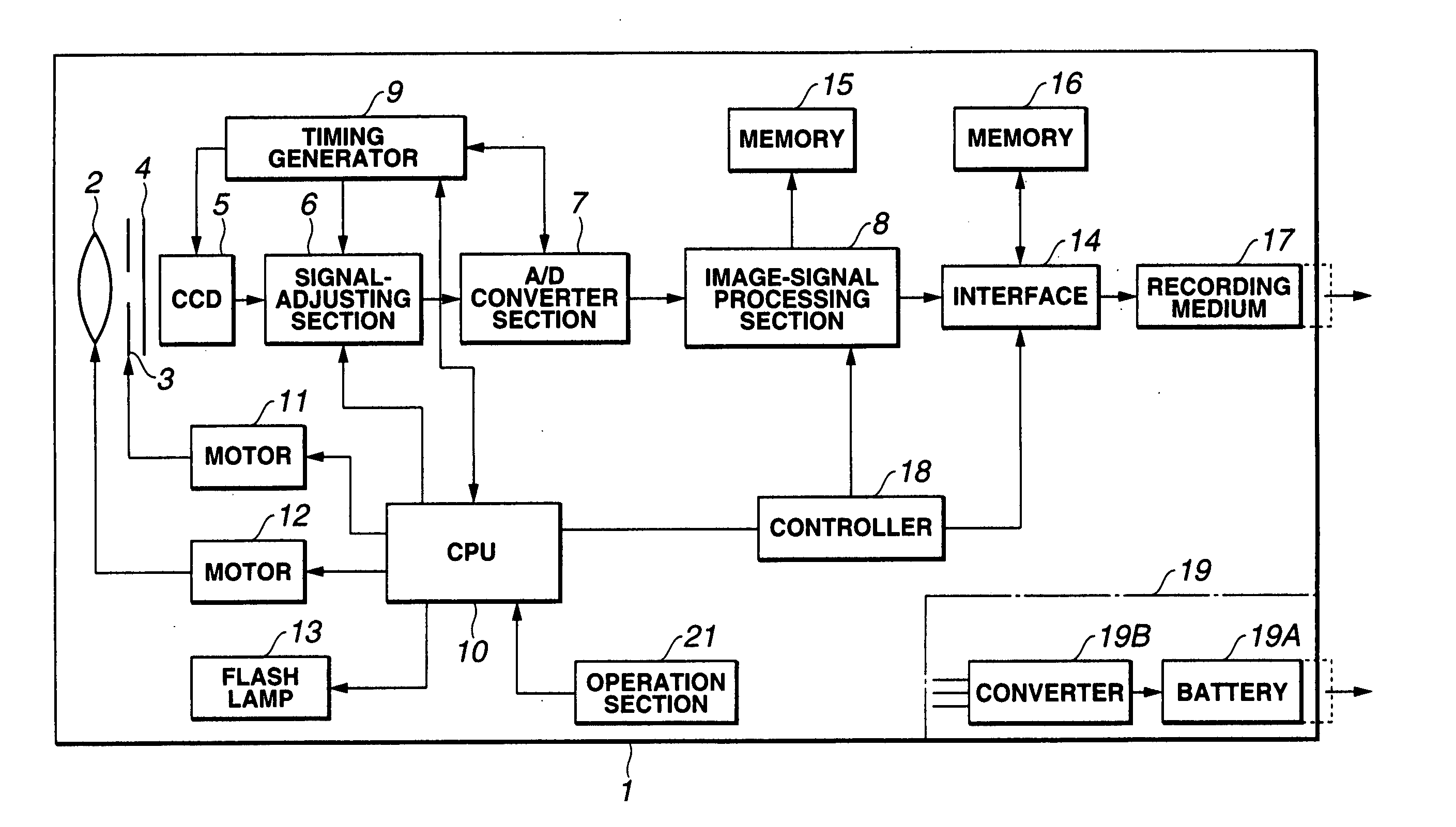
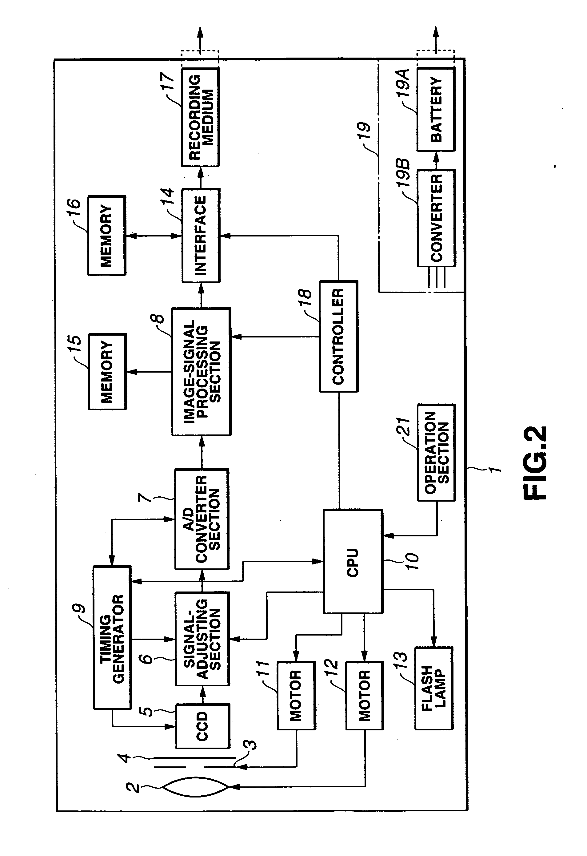
[0082] The present invention is applied to, for example, a digital still camera 1 of the type shown in FIG. 2. The digital still camera 1 is a single-plate camera designed to taking color pictures. The camera 1 comprises a color-coding filter 4 and one CCD image sensor 5. The color-coding filter 4 is arranged in front of the CCD image sensor 5 and composed of color filers, each provided for one pixel. A lens 2 focuses the light reflected from a picked image. The light is applied to the CCD image sensor 5 through an iris 3 and the color-coding filter 4. An image of the object is thereby formed on the image-forming surface of the CCD image sensor 5. The color-coding filter 4 and the CCD image sensor 5 are components separated from each other in the digital still camera 1. Nonetheless, they may be combined into one unit.

[0083] The CCD image sensor 5 rec...


PUM


Abstract

An image signal generated by a CCD image sensor is processed by the block-generating section 28 provided in an image-signal processing section 25. A class tap and a prediction tap are thereby extracted. The class tap is output to an ADRC process section 29, and the prediction tap is output to an adaptation process section 31. The ADRC process section 29 performs an ADRC process on the input image signal, generating characteristic data. A classification process section 30 generates a class code corresponding to the characteristic data thus generated and supplies the same to an adaptation process section 31. The adaptation process section 31 reads, from a coefficient memory 32, the set of prediction coefficients which corresponds to the class code. The set of prediction coefficients and the prediction tap are applied, thereby generating all color signals, i.e., R, G and B signals, at the positions of the pixels which are to be processed.

Description

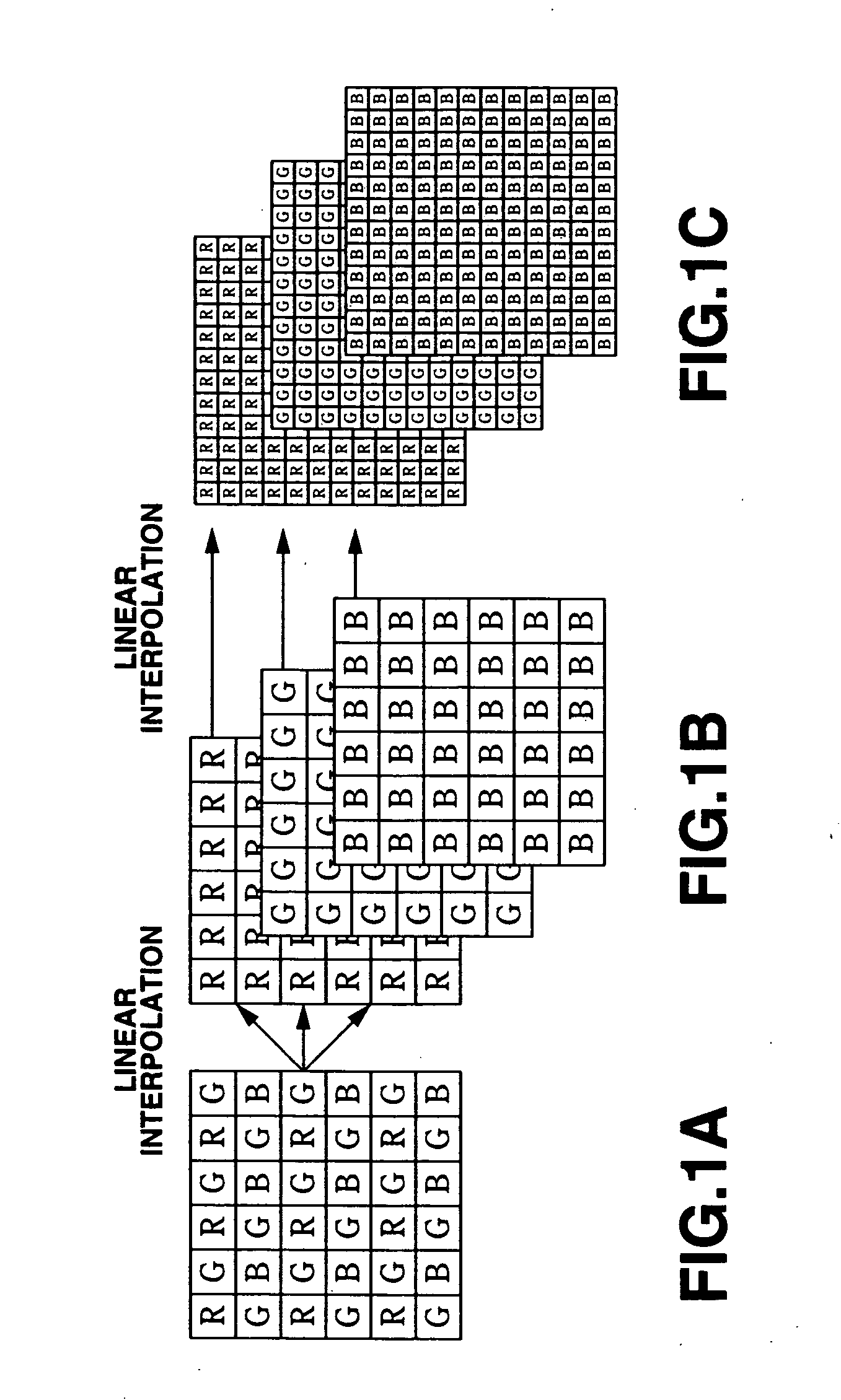
TECHNICAL FIELD [0001] The present invention relates to an image-signal processing apparatus, an image-signal processing method, a learning apparatus, a learning method, and a recording medium. More particularly, the invention relates to an image-signal processing apparatus, image-signal processing method, learning apparatus, a learning method and recording medium in which the color components of a pixel represented by an image signal are interpolated by means of classification-adaptation process so that the pixel may have a red (R) component, a green (G) component and a blue (B) component. BACKGROUND ART [0002] There are two types of imaging apparatuses that have a solid-state image sensor such as a CCD (Charge Coupled Device) image sensor. The first type has one CCD image sensor (hereinafter, referred to as “single-plate camera”). The second type has three CCD image sensors (hereinafter, referred to as “three-plate camera”). [0003] In a three-plate camera, the three CCD image sens...

Claims


Application Information

Patent Timeline
Patent Type & Authority Applications(United States)
IPC IPC(8): H04N23/12G06T9/00H04N7/26H04N7/46
CPCH04N9/045H04N19/59H04N19/98H04N2209/046H04N23/843H04N25/134H04N25/135H04N25/133H04N23/12
Inventor KONDO, TETSUJIRONAKAYA, HIDEOSAWAO, TAKASHI
Owner SONY CORP
Learn More