Fluidic scanner nozzle and spray unit employing same

a technology of fluidic scanner and spray unit, which is applied in the direction of spray nozzle, spray apparatus, etc., can solve the problems of reducing flow, changing spray pattern, clogging of deposit head, etc., and achieves economic and effective sealing, large coverage area, and reliably generating spray

Active Publication Date: 2021-12-07
DLHBOWLES INC
View PDF41 Cites 0 Cited by
  • Summary
  • Abstract
  • Description
  • Claims
  • Application Information

AI Technical Summary

Benefits of technology

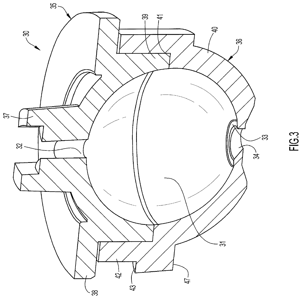
[0018]Fluidic scanner nozzles of the present invention overcome the difficulties described above by providing outlet orifice configurations that permit nozzle designers to achieve differently and selectively aimed scanning sprays that have particular utility in fluidic showerheads. The geometries of the scanner nozzles and their methods of manufacture permit use of a minimum of parts and provide for economical and effective sealing between parts. More specifically, plural scanner nozzles, or parts thereof, may be molded in simple open and close tooling as one piece in a scanner array with the individual nozzles configured to have their respective spray configurations predeterminedly aimed to effect a desired overall spray pattern from the array. Still more specifically, the outlet orifice or “throat” portions of the scanner nozzles in the array are molded with appropriate aiming configurations as one piece. The nozzle aim angle variations across the array allows for nozzle assemblies capable of reliably generating sprays with larger coverage areas and more uniform droplet coverage across a target area. The particular advantage of this method of aiming or yawing the sprays is that, when molding the scanner array, a very simple shutoff, perpendicular to the draw of the mold, is maintained over all scanners in the array. This is also an advantage, though not as great, when making even a single aimed scanner nozzle outlet orifice geometry.
[0021]In accordance with the present invention, outlet parts of an array of fluidic scanner nozzles may be molded in a single molded piece whereby different individual scanner nozzles can have different respective aim angles. The aim angle variation across the array allows for nozzle assemblies capable of reliably generating sprays with larger coverage areas and more uniform sprayed fluid droplet coverage across a target area.
[0023]In accordance with another aspect of the invention a plurality of the modified scanner oscillator nozzles are deployed in an array in a spray unit, such as a showerhead. The designed aim angles of the nozzles and their positions in the array permit the spray unit designer to preselect desired overall spray patterns. A given spray pattern provided by the array of the aimed scanner nozzles can be produced by fewer nozzles than the number of openings required for a conventional spray head that issues parallel static streams. As a result, the spray head with the aimed scanner nozzles may be smaller than conventional spray heads and, since fewer nozzles are used, the amount of water required to cover a given target is less.

Problems solved by technology

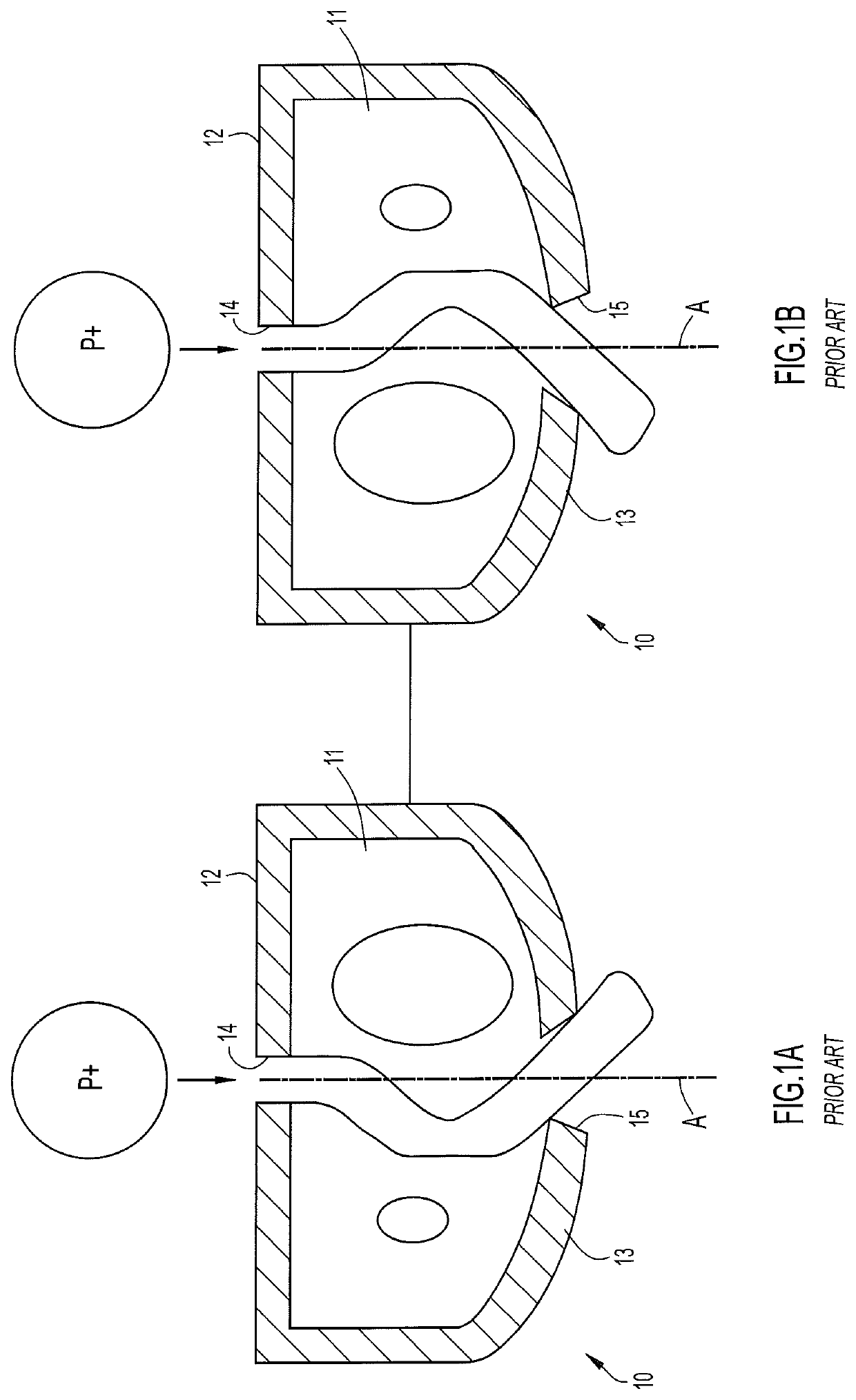
Another consideration is the fact that hard water may result in calcium and magnesium deposits clogging the head, reducing the flow and changing the spray pattern.
However, such outlets in showerheads issue straight jets that continuously impact essentially the same location on a user's skin, often causing a stinging type discomfort.
Rain can spray heads represent an effort to reduce this discomfort by enlarging the area emitting the sprays; however, the resulting spray is often too gentle for many users who enjoy a shower spray that produces a pleasant but not painful impact on the body without discomfort.
Unfortunately, it is not a trivial matter to replace several nozzles generating static jets with plural fluidic oscillators.
Fluidic scanner nozzle inserts are also sensitive to such turbulence, as well as to problems pertaining to sealing each insert in the housing.
Therefore, a traditional showerhead incorporating the above-described fluidic elements likely may not spray as intended because turbulent inlet or manifold flow disrupts the operation of fluidic oscillators.
Although that showerhead is quite satisfactory for most purposes, neither that showerhead nor any of those described in the other above-cited patents provides arrays of fluidic scanner nozzles in a single molded piece having varying aim angles to permit predetermined contouring of overall combined spray patterns.
There is also no disclosed approach to reliably providing larger coverage areas and more uniform coverage across the target area.
Finally, there is no practical way disclosed in the prior art of making the egress orifice throat side of the multi-nozzle scanner array in one piece.

Method used


Image

  • Fluidic scanner nozzle and spray unit employing same
  • Fluidic scanner nozzle and spray unit employing same
  • Fluidic scanner nozzle and spray unit employing same

Examples


Embodiment Construction

[0047]Specific dimensions set forth below are by way of example for particular embodiments to assist in an understanding of the illustrated structure; these dimensions are not to be construed as limiting the scope of the invention.

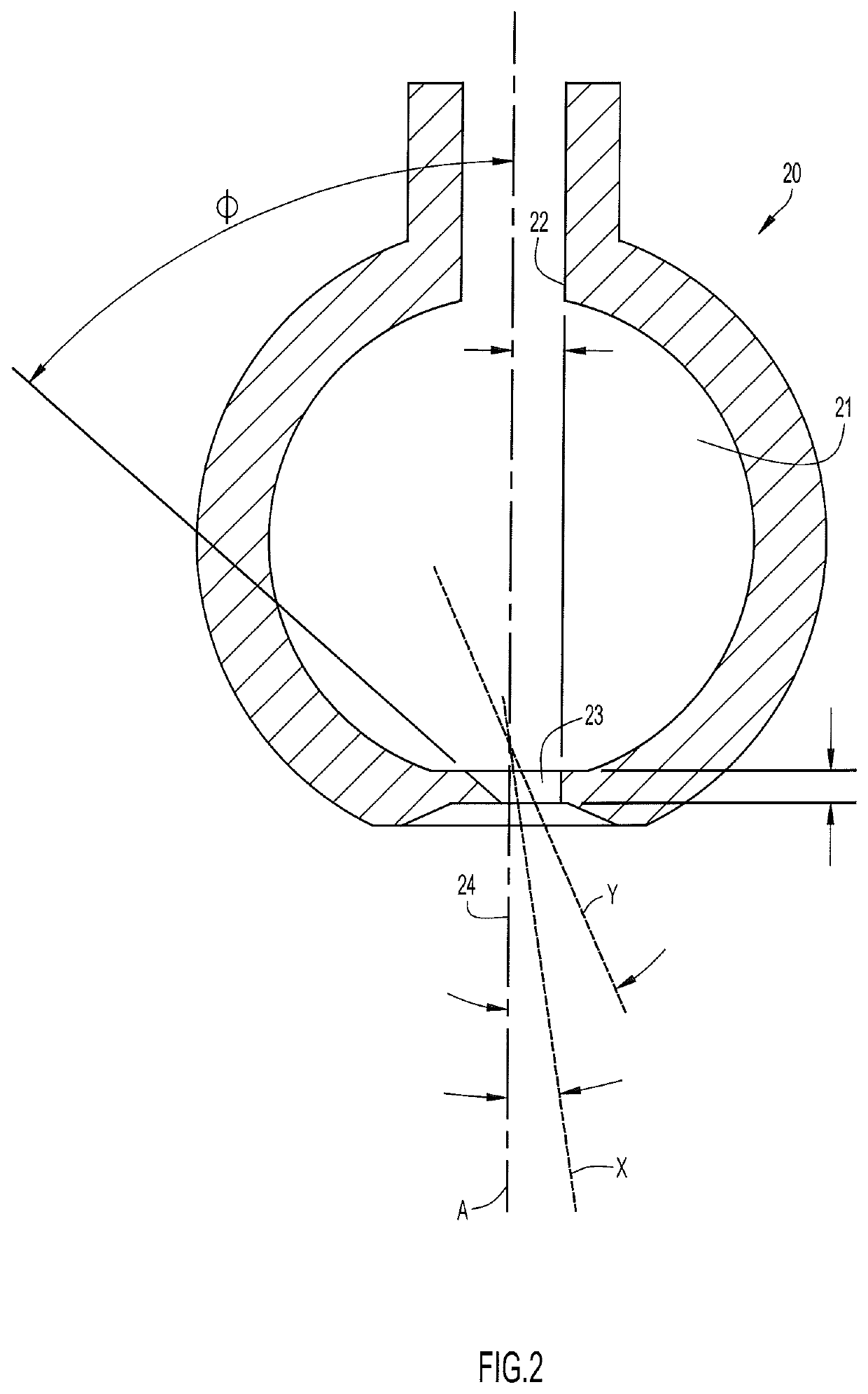
[0048]Referring specifically to FIG. 2 of the accompanying drawings, a fluidic scanner oscillator 20 comprises an interaction chamber 21 of substantially spherical configuration and having a longitudinal axis A. An inlet lumen 22 is disposed preferably concentrically about axis A and is typically connected to a source of pressurized liquid to deliver a jet of the liquid into the upstream end of the chamber. Substantially diametrically opposed to the inlet lumen is an outlet orifice or aperture 23 for issuing the liquid jet to the surrounding ambient environment through a short annular collar region 24 defined as a recess in the outer surface of the chamber wall and diverging from orifice 23.

[0049]The periphery of outlet orifice 23 is configured as an irreg...


PUM


Abstract

A fluidic nozzle of the scanner type has its outlet spray pattern skewed from its chamber axis (A) by an amount determined by the asymmetry of its outlet orifice (23, 33) about that axis. A spray assembly (70, 90) of such nozzles, such as a showerhead, can be designed using nozzles with selected pattern skew angles to achieve desired spray coverage. Indexing tabs (97) and slots (96) are used to angularly position the nozzles in the showerhead. A portion of each nozzle may be formed with the showerhead faceplate (71) as an integral piece.

Description

CROSS REFERENCE TO RELATED APPLICATIONS[0001]The present application is a 35 U.S.C. 371 national stage filing and claims priority to and the benefit of International Application No. PCT / US2017 / 030813 filed on May 3, 2017, which is a non-provisional application of and claims priority to U.S. Provisional Application No. 62 / 330,930, entitled “Scanner Nozzle Aim Structure and Method, Aimed Scanner Nozzle Array and Method,” filed May 3, 2016, the disclosure of which are hereby incorporated by reference herein in their entirety.BACKGROUNDTechnical Field[0002]The present invention pertains generally to methods and apparatus for fluidically generating desired fluid spray patterns, primarily liquid patterns sprayed in droplets to reliably wet a target area. In a more particular aspect, the invention pertains to enhancements to fluidic oscillator nozzles, their use in spray assemblies (e.g., showerheads) configured to generate a plurality of predeterminedly aimed three-dimensional oscillating...

Claims


Application Information

Patent Timeline
Patent Type & Authority Patents(United States)
IPC IPC(8): B05B1/18B05B1/08
CPCB05B1/185B05B1/08
Inventor RUSSELL, GREGORY A.HESTER, RUSSELL
Owner DLHBOWLES INC
Why Eureka
Try Eureka