Method for aligning a system, and system for detecting position data of at least one element in the front region of an eye

a front region and eye technology, applied in the field of system alignment and system alignment, can solve the problems of inability to follow up correction, local inaccuracy, and oculomotor system impair the integrity and continuity of the process, and achieve the effect of reliably generating diagnostic data sets and/or data sets

Active Publication Date: 2019-05-28
HEIDELBERG ENGINEERING GMBH
View PDF21 Cites 0 Cited by
  • Summary
  • Abstract
  • Description
  • Claims
  • Application Information

AI Technical Summary

Benefits of technology

[0008]It is therefore an object of the invention to provide a method for aligning a system and a system for detecting position data of at least one element in the front region of an eye, which ensure continuous adaptation to movements of the eye so as to reliably generate diagnostic data sets and / or data sets for material changes.
[0009]The method according to the invention in accordance with the species mentioned at the outset provides a continuous detection of position changes of least one distinct location and / or at least one distinct structure on the cornea and / or on the region of an eye located behind the cornea by aligning the first system component with this location or with this structure, and further includes directing electromagnetic radiation at topographical structures of the cornea to be ascertained or to be modified by aligning the second system component, characterized in that the alignment of the first system component with respect to the alignment of the second system component is defined, and the second system component is continuously guided to the respective target position thereof based on the position changes detected by the first system component. According to the invention, the detected information allows continuous tracking of the diagnostic and / or treatment system.
[0013]However, on the other hand it also has advantages if multiple light sources are disposed symmetrically around the main axis of the system. It is then possible to use the positions of the reflection points caused by the light sources on the eye to determine an at least approximate position of the vertex. This is because a symmetrical arrangement of the light sources around the main axis of the system creates a symmetrical pattern of reflection points, wherein an origin of symmetry of the arrangement of the reflection points at least approximately corresponds to the position of the vertex. The origin of symmetry can be determined with the aid of a convolution. Such a method can be implemented very quickly and without major complexity.
[0014]The vertex can thus be determined with sufficient precision by way of the reflection points. However, a parallax error arises if the vertex is not located on the optical main axis. This parallax error can be corrected if the radius of the curvature of the cornea is known. Human corneas do not vary significantly in the radius of curvature; they exhibit values between 7 mm and 9 mm, so that the parallax correction is relatively good if it is determined for a sphere having a diameter of 8 mm.
[0019]According to one variant according to the invention, it may be provided in the method that the quality of the cornea surface and / or the condition of the precorneal film on the surface of the cornea are ascertained based on the quality of the reflection points. While tracking, if it is carried out in accordance with the present invention, is relatively precise and robust to begin with, it may result in smaller jumps, for example when the precorneal film is disrupted. These inaccuracies can be prevented by a quality check.
[0022]In this way, arbitrary scan patterns, such as rasters or meridians, can now be recorded. In particular, it is ensured that meridian sections extend through the vertex, and a refraction correction can take place in one plane. Topographies can be recorded without subsequent lateral movement tracking. Axial movements are easy to calculate, since all deep sections have a common point, in particular in the case of meridian scan patterns.

Problems solved by technology

During the examination or the treatment of the front region of the eye by way of chronologically serial diagnostic and / or treatment processes, which generally consist of multiple steps, the oculomotor system impairs the integrity and continuity of the process, be it arbitrarily or involuntarily, consciously or unconsciously.
While subsequent corrections and / or tracking are possible for diagnostic data, they contain inhomogeneous information densities in the case of strong movements, resulting in local inaccuracies.
For treatment systems, subsequent correction is not practical.

Method used


Image

  • Method for aligning a system, and system for detecting position data of at least one element in the front region of an eye
  • Method for aligning a system, and system for detecting position data of at least one element in the front region of an eye
  • Method for aligning a system, and system for detecting position data of at least one element in the front region of an eye

Examples


Embodiment Construction

[0035]Example embodiments will now be described more fully with reference to the accompanying drawings.

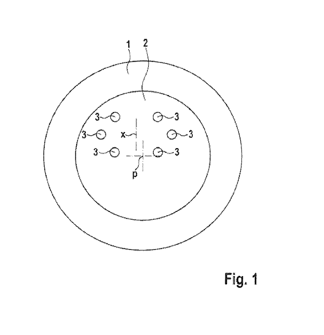
[0036]FIG. 1 shows a schematic illustration of the front region of a human eye, in which a pupil 2 is surrounded by an iris 1. p denotes the center of the pupil. In a system according to the invention, light sources are symmetrically disposed around the main axis of the diagnostic and / or treatment system, resulting in a pattern of reflection points 3. The center x of the reflection points 3 corresponds approximately to the vertex of the eye. The position of the vertex of the eye is also dependent on the fixation and fixation axis. If the position of the pupil 2 or of the pupil center p in relation to the center x of the reflection points 3 is tracked, fixation can be monitored, and a loss of fixation resulting in misalignment of the eye can be detected.

[0037]This monitoring is useful in particular for systems that ascertain geometric information of the front region of the eye seque...


PUM


Abstract

A system for detecting position data of an element in the front region of an eye. A first system component continuously detects position changes of the vertex of the cornea of the eye. A second system component directs electromagnetic radiation at topographical structures of the cornea to be ascertained or modified. A control unit includes a processor and memory. Alignment of the first system component with respect to the alignment of the second system component is defined, and the second system component is continuously guided to the respective target position thereof, by the control unit based on the position changes detected by the first system component. Light sources, which illuminate the cornea, are symmetrically disposed around the main axis of the system so that a pattern of reflection points is created on the cornea. The processor determines the current position of the vertex as the center of the reflection points.

Description

CROSS-REFERENCE TO RELATED APPLICATIONS[0001]This application is a National Stage of International Application No. PCT / DE2014 / 100108, filed Mar. 28, 2014. This application claims the benefit and priority of German application 10 2013 106 420.5, filed Jun. 19, 2013. The entire disclosures of the above applications are incorporated herein by reference.BACKGROUND[0002]This section provides background information related to the present disclosure which is not necessarily prior art.[0003]Technical Field[0004]The invention relates to a method for aligning a system for detecting position data of at least one element in the front region of an eye, wherein the system comprises at least one first system component and a second system component. The invention further relates to a system for detecting such position data.[0005]Discussion[0006]Such a method and such a system are known from DE 10 2009 030 466 A1. In preparation for refractive laser treatment of the eye, initially the current data o...

Claims


Application Information

Patent Timeline
Patent Type & Authority Patents(United States)
IPC IPC(8): A61B3/11A61B3/107A61B3/10A61F9/008A61B3/113
CPCA61B3/113A61B3/102A61F9/008A61B3/112A61B3/107
Inventor ENGELHARDT, RALFMARTENSEN, BJORN
Owner HEIDELBERG ENGINEERING GMBH
Why Eureka
Try Eureka