Backlight unit

a backlight unit and light-type technology, applied in the field of backlight units, can solve the problems of low optical efficiency of conventional backlight units, high manufacturing costs, and large number of assembly steps, and achieve the effect of improving brightness uniformity and reducing the range of azimuth angles

Active Publication Date: 2005-09-15
SAMSUNG DISPLAY CO LTD
View PDF7 Cites 34 Cited by
  • Summary
  • Abstract
  • Description
  • Claims
  • Application Information

AI Technical Summary

Benefits of technology

[0017] The present invention provides an edge light type backlight unit with brightness uniformity improved by decreasing the range of azimuth angles of light emitted by a light source on a light guide panel.

Problems solved by technology

Thus, the conventional backlight unit suffers from low optical efficiency, large number of assembling steps, and high manufacturing costs.

Method used


Image

  • Backlight unit
  • Backlight unit
  • Backlight unit

Examples


Embodiment Construction

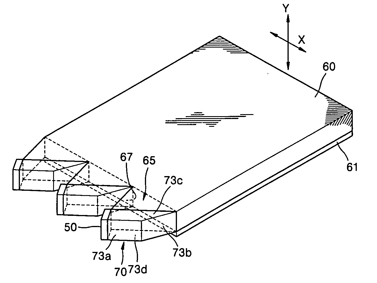
[0033] Referring to FIGS. 6 and 7, a backlight unit according to a first embodiment of the present invention includes one or more light sources 50, a light guide panel 60 that guides the propagation of light incident on one side edge 60a thereof, one or more light-reception portion 65 disposed along the side edge 60a of the light guide panel 60, and one or more reflecting elements 70 disposed between the light-reception portion 65 and each of the light sources 50.

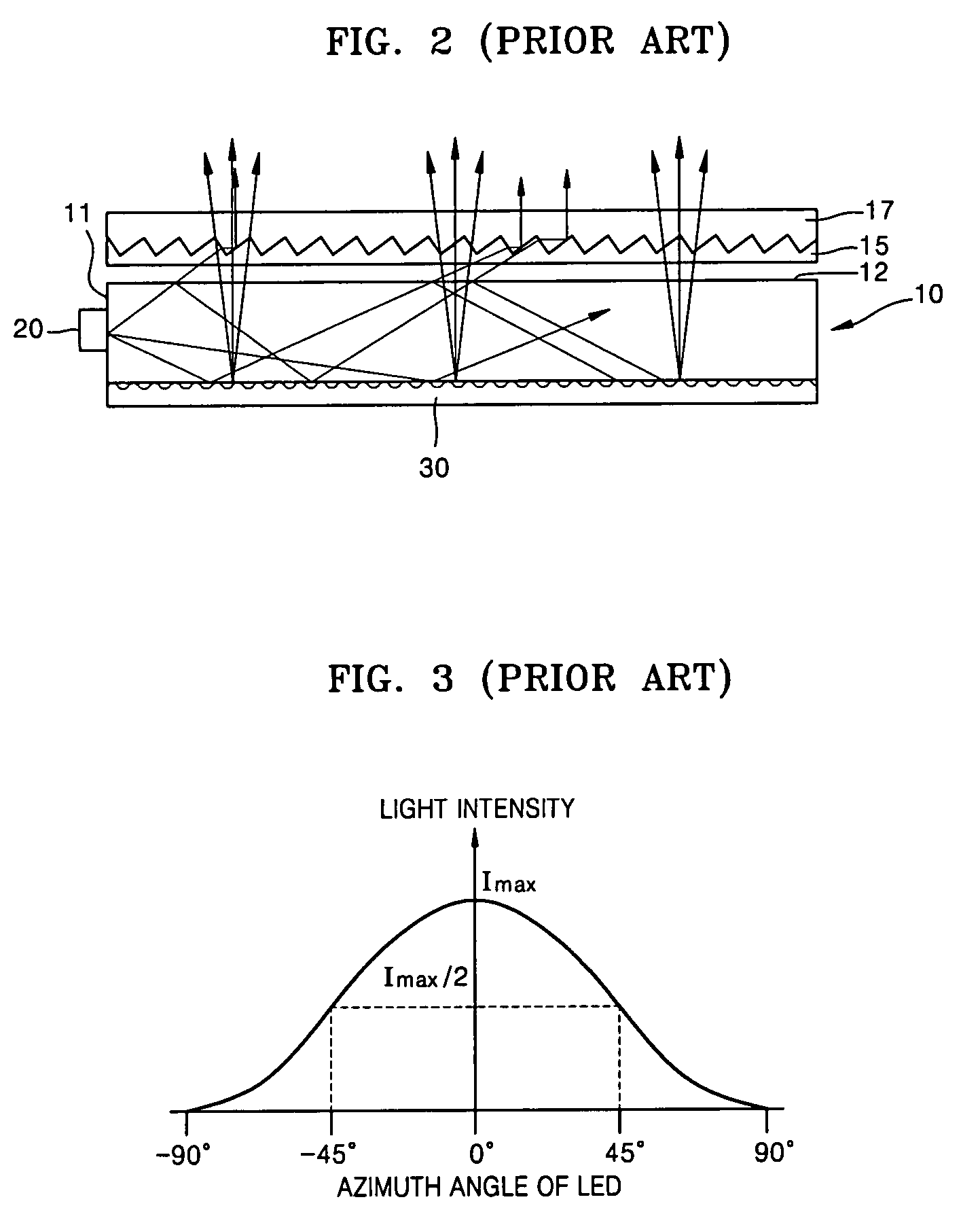
[0034] The light source 50 may be a point light source such as a light emitting diode (LED) or a linear light source such as a cold cathode fluorescent lamp (CCFL) and emits light on one side of the light guide panel 60. FIG. 6 shows an example of using three LEDs as the light source 50. In this case, corresponding light source 50 and reflecting element 70 are provided for each LED. The LED emits the light in an angular range between −90° and +90° about an optical axis. The LED has a forward half maximum (FWHM) angle betwe...


PUM

PropertyMeasurementUnit
included angle θ1aaaaaaaaaa
included angle θ2aaaaaaaaaa

Abstract

An edge light type backlight unit having an improved light-reception portion. The backlight unit includes one or more light sources that emit light, a light guide panel that guides the propagation of light incident on one side edge thereof, one or more light-reception portions having a first entrance face slanted opposite the side edge of the light guide panel on which the light is incident at a predetermined angle, and one or more reflecting elements that are disposed between each of the light-reception portions and each of the light sources and guides the light emitted by the light source so that it is incident on the first entrance face.

Description

BACKGROUND OF THE INVENTION [0001] This application claims priority from Korean Patent Application No. 10-2004-0004562, filed on Jan. 24, 2004, in the Korean Intellectual Property Office, the disclosure of which is incorporated herein in its entirety by reference. [0002] 1. Field of the Invention [0003] The present invention relates to an edge light type backlight unit, and more particularly, to a backlight unit having an improved light-reception portion. [0004] 2. Description of the Related Art [0005] Typically, a liquid crystal display (LCD) device is one of light-reception flat panel displays and needs a separate light source to produce an image since the LCD itself does not emit light. To this end, a backlight unit is located behind the LCD device and emits light. The backlight units are used in LCD devices as well as in surface light source systems such as illuminating signs. [0006] Backlight units are classified into direct light type units and edge light type units according ...

Claims


Application Information

Patent Timeline
Patent Type & Authority Applications(United States)
IPC IPC(8): G02F1/13357F21V7/04F21V8/00F21Y101/02
CPCG02B6/0028G02B6/0068G02B6/0046B44C5/02C11C5/008
Inventor NESTERENKO, DMITRIKIM, SUN-ILCHOI, YOON-SUNLEE, SU-MIYOU, KYUNG-HEEMIN, JEE-HONG
Owner SAMSUNG DISPLAY CO LTD
Why Eureka
Try Eureka