
Server apparatus, network-based appliance, and program product

a network-based appliance and server technology, applied in the field of server apparatus, can solve the problems of difficult shape and use form, inability to provide input parts for such communication parameters with keys, and inability to provide them in most cases, so as to achieve smooth and easy setting of wireless lan communication parameters

Inactive Publication Date: 2005-09-15
SANYO ELECTRIC CO LTD
View PDF20 Cites 74 Cited by
  • Summary
  • Abstract
  • Description
  • Claims
  • Application Information

AI Technical Summary

Benefits of technology

The present invention provides a network system that allows for easy and smooth setup of wireless LAN communication parameters for appliances connected to an internal network. The server apparatus can communicate with the appliance either through an internal network or directly through a wireless network. The server apparatus can obtain the necessary communication parameters from an external network and store them locally for use in communication with the appliance. The server apparatus can also transmit the necessary parameters to the appliance through the internal network or directly through the wireless network. The invention ensures secure communication between the server apparatus and the appliance. Overall, the invention simplifies the process of setting wireless LAN communication parameters for appliances connected to an internal network.

Problems solved by technology

However, in appliances of white goods such as a washing machine and a refrigerator, an input part for inputting such communication parameters with keys is not provided in most cases.
However, providing the above-mentioned interface and display apparatus separately in white goods such as a washing machine and a refrigerator and a network adaptor that provides a function for a network to other household electric appliances only for the purpose of setting wireless LAN communication parameters is not a good idea in terms of cost and the like, and providing them may be difficult in terms of a shape and a use form.

Method used


Image

  • Server apparatus, network-based appliance, and program product
  • Server apparatus, network-based appliance, and program product
  • Server apparatus, network-based appliance, and program product

Examples


first embodiment

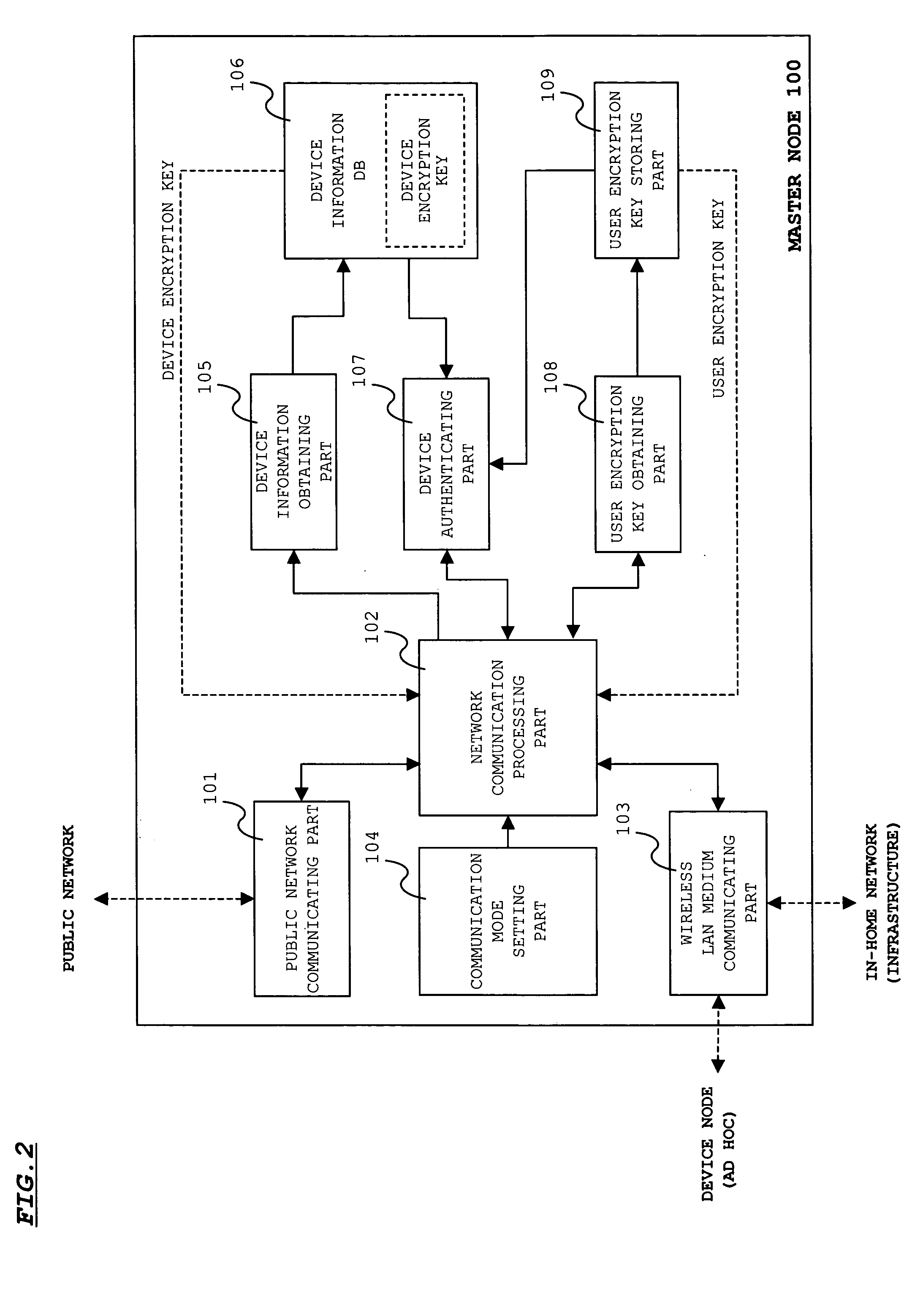
[0041]FIG. 2 shows functional blocks of the master node 100.

[0042]FIG. 2 shows only functional blocks required for giving a user encryption key. These functions can be realized by installing a program or a database for allowing a CPU to execute these functions in cooperation in the master node 100. The program or the database can be installed by a downloading method via a public network such as the Internet or a method for appropriately loading a storage medium (disk, etc.) storing the program or the database.

[0043] As shown in FIG. 2, the master node 100 includes a public network communicating part 101, a network communication processing part 102, a wireless LAN medium communicating part 103, a communication mode setting part 104, a device information obtaining part 105, a device information DB (database) 106, a device authenticating part 107, a user encryption key obtaining part 108, and a user encryption key storing part 109.

[0044] The public network communicating part 101 inc...

second embodiment

[0067] In the above-mentioned first embodiment, a search command is broadcast through radio waves (ad hoc mode), so that it is necessary that the new device node 200 and the master node 100 be provided in a range where radio waves reach directly. However, there may be a setting form in which the new device node 200 and the master node 100 are provided in such a manner that radio waves do not reach directly, e.g., the case where the new device node 200 and the master node 100 are provided respectively on the first and third floors. In such a case, in the first embodiment, it is impossible to set a user encryption key in the new device node 200. This embodiment overcomes such inconvenience.

[0068] In this embodiment, a search function of a new device node in the above first embodiment and a function of giving a user encryption key are distributed to the device node 200 that has already been connected to an in-home network. More specifically, the function of the device authenticating p...

third embodiment

[0078] This embodiment relates to processing in changing a user encryption key that has already been set.

[0079]FIG. 8 shows a processing flow of the master node 100 according to this embodiment.

[0080] When a user inputs an instruction of changing a user encryption key and a new user encryption key by operating an operation terminal, the master node 100 sets reset flags of all the device nodes stored in the device information DB 106 to “1” (S301), and broadcasts a reset command in an infrastructure mode designating to all the device nodes (device nodes in which reset flag=1) (S302). The device node 200 having received such a reset command transmits a reception response of the reset command to the master node 100 in an infrastructure mode, and thereafter, erases the user encryption key stored in its own user encryption key storing part 207, and switches a communication mode to an ad hoc mode based on its own device encryption key.

[0081] Upon receiving the reception response of the ...


PUM


Abstract

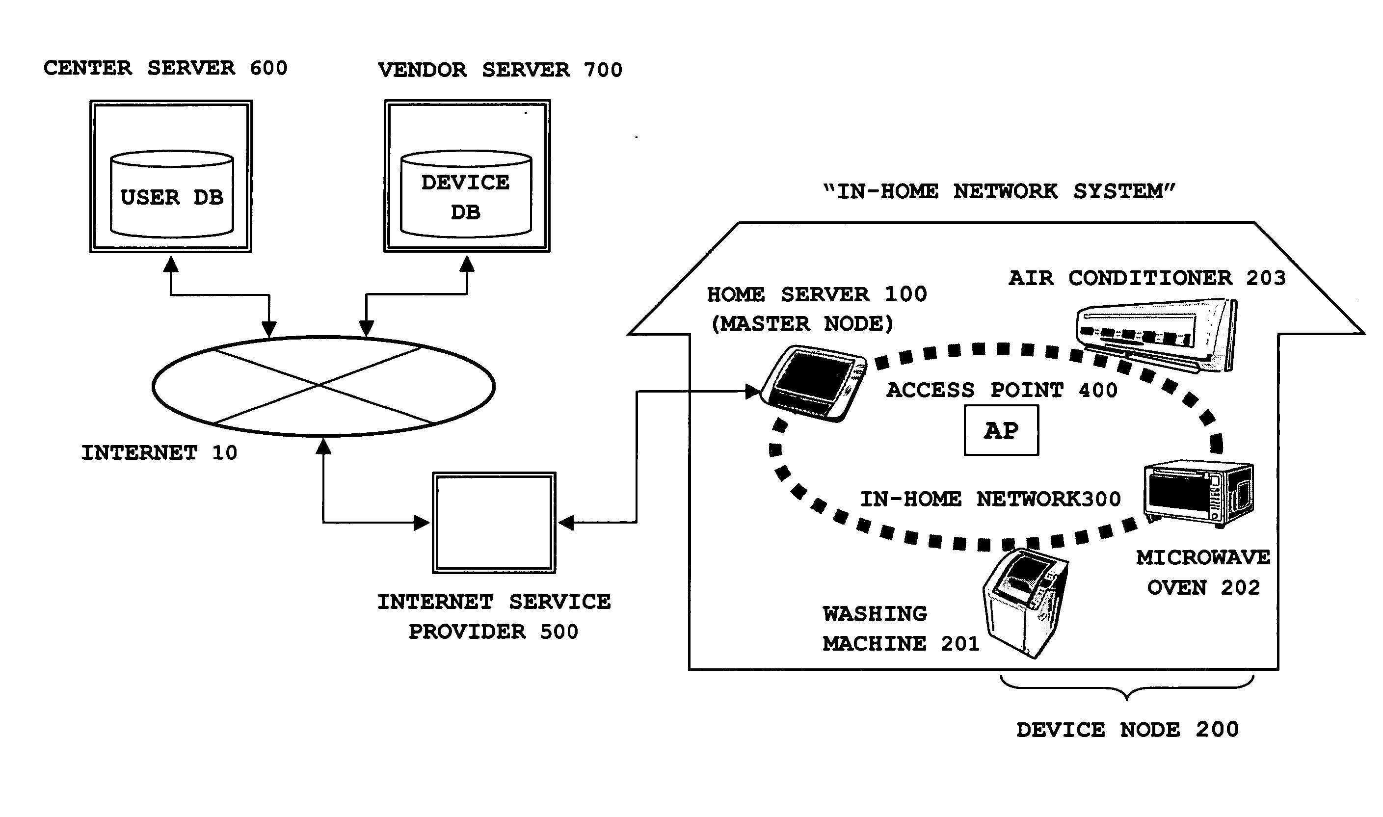
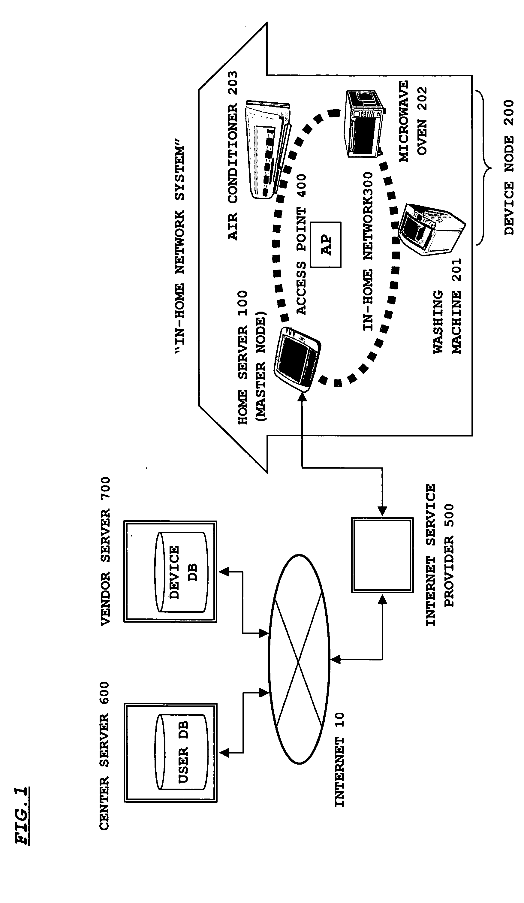
An object of the present invention is to set a wireless LAN communication parameter with respect to an appliance connected to an in-home network smoothly and easily. Prior to purchasing an appliance, a user registers an in-home network in a center server, and receives a user ID and an e-mail address. Thereafter, when the user purchases an appliance from a vendor by presenting his / her own user ID, a user ID and a device encryption key of the appliance are transmitted from the vendor to the center server. The center server transmits the received information to an e-mail address (home server) of the user ID. The home server searches for a corresponding appliance in an ad hoc mode using the received device encryption key. At this time, when the purchased appliance has already been on the network, communication is established, and a user encryption key (wireless communication parameter) is given from the home sever to the appliance.

Description

BACKGROUND OF THE INVENTION [0001] 1. Field of the Invention [0002] The present invention relates to a server apparatus, a network-based appliance, and a program product, and more particularly to a server apparatus, a network-based appliance, and a program product preferably used in an in-home network system using a wireless LAN as a transmission medium. [0003] 2. Description of the Related Art [0004] In recent years, a wireless LAN is becoming mainstream as a transmission medium for an in-home network. In the case of using a wireless LAN as a transmission medium, it is necessary to set wireless LAN communication parameters (encryption key information such as an ESS-ID and a WEP key, etc.) required for wireless LAN communication on an appliance side, in participation in an in-home network. [0005] However, in appliances of white goods such as a washing machine and a refrigerator, an input part for inputting such communication parameters with keys is not provided in most cases. In suc...

Claims


Application Information

Patent Timeline
Patent Type & Authority Applications(United States)
IPC IPC(8): H04L9/32H04L9/08H04L12/28H04W84/12H04W84/20H04W88/08H04W92/08
CPCH04L12/2807H04L12/2818H04L41/0806H04L2012/285H04L63/062H04L2012/2841H04L63/0428
Inventor HATAYAMA, YOSHINORIOHNARU, SHINICHIHIRATA, TOSHIYUKI
Owner SANYO ELECTRIC CO LTD
Learn More