Temperature measurement

a technology of temperature measurement and measurement area, applied in the field of temperature measurement, can solve the problems of inaccurate readings, inaccurate measurement, and inaccurate measurement of surface temperature, and achieve the effect of accurate measurement of surface temperatur

Inactive Publication Date: 2005-09-15
HOLLANDER MILTON BERNARD +1
View PDF26 Cites 22 Cited by
  • Summary
  • Abstract
  • Description
  • Claims
  • Application Information

AI Technical Summary

Benefits of technology

[0032] It is another object of the present invention to provide such a method and apparatus which provides more accurate measurement of the surface temperature than provided by the use of techniques heretofore employed.
[0033] It is yet another object of the present invention to provide such a method and apparatus which permits the user visually to identify the location, size nd temperature of the energy zone on the surface to be measured.
[0035] It is a still further object of the present invention to provide a method and apparatus which permits the use of a single laser beam which is subdivided by passing it through, or over, a beam splitter, holographic element or a diffraction grating, thereby to form a plurality of three or more subdivision beams which provide a pattern where they strike a target whose energy zone is to be investigated.

Problems solved by technology

Heretofore, there have been no means of accurately determining the perimeter of the actual energy zone unless it is approximated by the use of a “distance to target table” or by actual physical measurement.
The use of a laser to pinpoint only the center of the energy zone does not, however, provide the user with an accurate definition of the actual energy zone from which the measurement is being taken.
This inability frequently results in inaccurate readings.
For example, in cases where the area from which radiation emits is smaller than the target diameter limitation (too far from or too small a target), inaccurate readings will occur.
In the case where the surface does not fill the entire energy zone area, the readings will be low and, thus, in error.
Similarly, if the surface is irregularly shaped, the readings will also be in error since part of the object would be missing from the actual energy zone being measured.
Thus, the use of a single laser beam only to the apparent center of the energy zone does not insure complete accuracy since the user of the radiometer does not know specifically the boundaries of the energy zone being measured.
This adds additional energy to the same energy zone where the temperature measurement is to be taken, and this destroys accuracy.
This manner of indication, utilizing incoherent multi-spectral light, has the disadvantage amongst others that the multi-spectral light itself has a heat factor which can cause incorrect reading by the energy detecting means of the apparatus.
It is not possible simply to substitute a laser for an incandescent light source, because the incandescent beam is incoherent in nature, so that when projected parallel and in close proximity to the boundaries of the invisible infra-red zone, incandescent light inside the infra-red zone is reflected as heat energy.
Moving the incandescent beam well away from the infra-red zone clearly does not permit accurate delineation of the target zone.

Method used


Image

  • Temperature measurement
  • Temperature measurement
  • Temperature measurement

Examples


Embodiment Construction

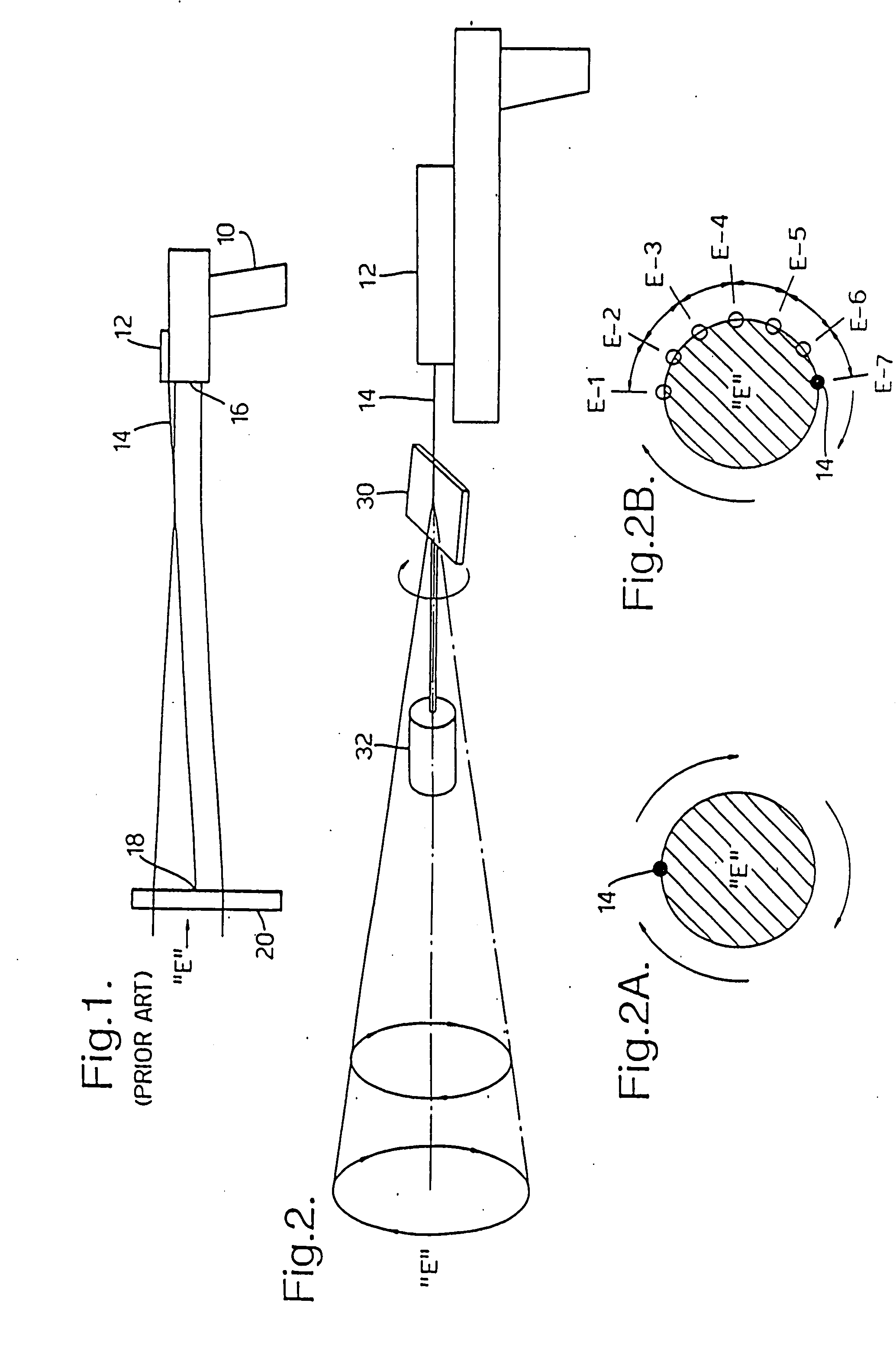
[0066] Traditionally, prior art radiometers have long employed laser sighting devices and direction finders to assist in the proper aim and alignment of the instrument. FIG. 1 illustrates and direction finders the operation of traditional, prior art, hand held radiometers. Such a radiometer, referred to generally by reference numeral 10, includes a laser sight scope 12 which emits a laser beam 14 to a spot or target 18 on the surface 20 whose temperature is to be measured. This spot 18 is located in the center of the energy zone “E” which is to be measured by the radiometer 10. The radiometer 10 includes a detector 16 which is connected to conventional internal circuitry and display means (not shown) for conversion, calculation and display of the temperature of the surface 20 calculated indirectly from the energy radiated from the surface within the energy zone E. Such energy is radiated in straight lines in all directions away from the surface 20 and captured with the detector 16 o...


PUM

PropertyMeasurementUnit
focal distanceaaaaaaaaaa
surface temperatureaaaaaaaaaa

Abstract

Method and apparatus are provided for visibly outlining the energy zone to be measured by a radiometer. The method comprises the steps of providing a laser sighting device on the radiometer adapted to emit more than two laser beams against a surface whose temperature is to be measured and positioning said laser beams about the energy zone to outline said energy zone. The apparatus comprises a laser sighting device adapted to emit more than two laser beams against the surface and means to position said laser beams about the energy zone to outline said energy zone. The laser beams may be rotated about the periphery of the energy zone. The laser beams may be rotated about the periphery of the energy zone. In another embodiment, a pair of laser beams are projected on opposite sides of the energy zone. The laser beams may be further pulsed on and off in a synchronized manner so as to cause a series of intermittent lines to outline the energy zone. Such an embodiment improves the efficiency of the laser and results in brighter laser beams being projected. In yet another embodiment, a primary laser beam is passed through or over a beam splitter or a diffraction grating so as to be formed into a plurality of secondary beams which form, where they strike the target, a pattern which defines an energy zone area of the target to be investigated with the radiometer. Two or more embodiments may be used together. A diffraction device such as a grating may be used to form multiple beams. In a further embodiment, additionally laser beams are directed axially so as to illuminate the center or a central are of the energy zone.

Description

RELATED APPLICATIONS [0001] This is a continuation-in-part application of both pending U.S. patent applications Ser. Nos. 08 / 764,659 filed on 11 Dec. 1996 and Ser. No. 08 / 617,265 filed on 18 Mar. 1996 in the names of Milton B. Hollander and W. Earl McKinley for Method and Apparatus for measuring Temperature Using Infrared Techniques, the latter of which, is a continuation-in-part application of U.S. application Ser. No. 08 / 348,978 filed on 28 Nov. 1994, now U.S. Pat. No. 5,524,984 which in turn was a continuation-in-part application of then copending U.S. patent application Ser. No. 08 / 121,916 filed 17 Sep. 1993, now issued as U.S. Pat. No. 5,368,392, on 29 Nov. 1994.BACKGROUND OF THE INVENTION [0002] 1. Field of the Invention [0003] The present invention relates generally to a method and apparatus for more accurately measuring the temperature of a surface using infrared measurement techniques and, more particularly, to such a method and apparatus which utilizes a laser sighting dev...

Claims


Application Information

Patent Timeline
Patent Type & Authority Applications(United States)
IPC IPC(8): G01J5/02G01J5/08
CPCG01J5/02G01J5/0265G01J5/0275G01J5/08G01J5/0896G01J5/084G01J5/0859G01J5/089G01J5/0809G01J5/0808G01J5/07
Inventor HOLLANDER, MILTON BERNARDMCKINLEY, WILLIAM EARL
Owner HOLLANDER MILTON BERNARD
Why Eureka
Try Eureka