Electrical connector

a technology of electrical connectors and connectors, applied in the direction of coupling contact members, coupling device connections, conductive pattern formation, etc., can solve the problems of reducing the reliability of connections, wiping action between conductors and mating surfaces, and high normal contact force drawbacks

Inactive Publication Date: 2005-09-15
METHODE ELETRONICS INC
View PDF69 Cites 22 Cited by
  • Summary
  • Abstract
  • Description
  • Claims
  • Application Information

AI Technical Summary

Problems solved by technology

Additionally, higher normal contact forces can cause wiping action between the conductor and the mating surface, when they are engaged in a sliding manner.
This wiping action can help remove debris that might be on the conductor or mating surface, which might otherwise reduce the reliability of the connection.
However, there can be drawbacks to high normal contact forces.
An operator, attempting to overcome such high insertion forces, may damage the connector.
Additionally, the wiping action associated with higher contact forces can cause wear of the conductor and / or mating surface, including removal of desirable coatings, which can lead to oxidation and poor electrical connections.
However, applicant appreciates that requiring the conductor to be optimized for both transmitting a current and applying a contact force in this manner often requires compromises to be made when choosing materials or configurations for conductors.

Method used


Image

  • Electrical connector
  • Electrical connector
  • Electrical connector

Examples


Embodiment Construction

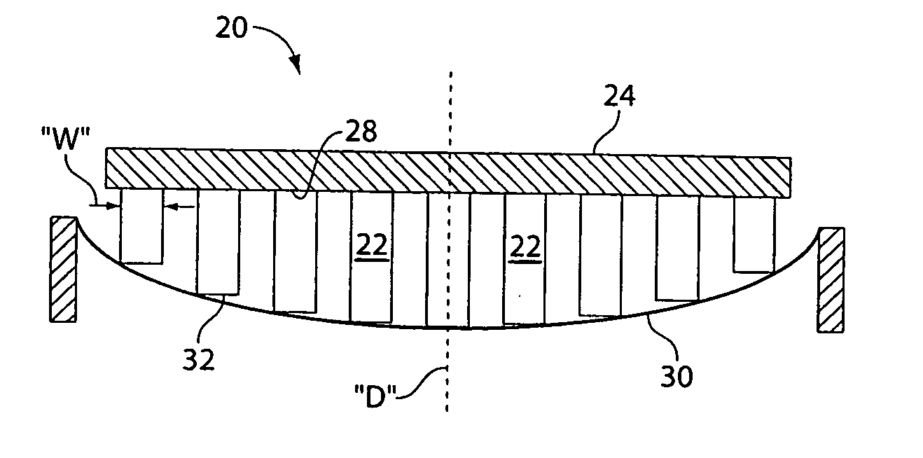
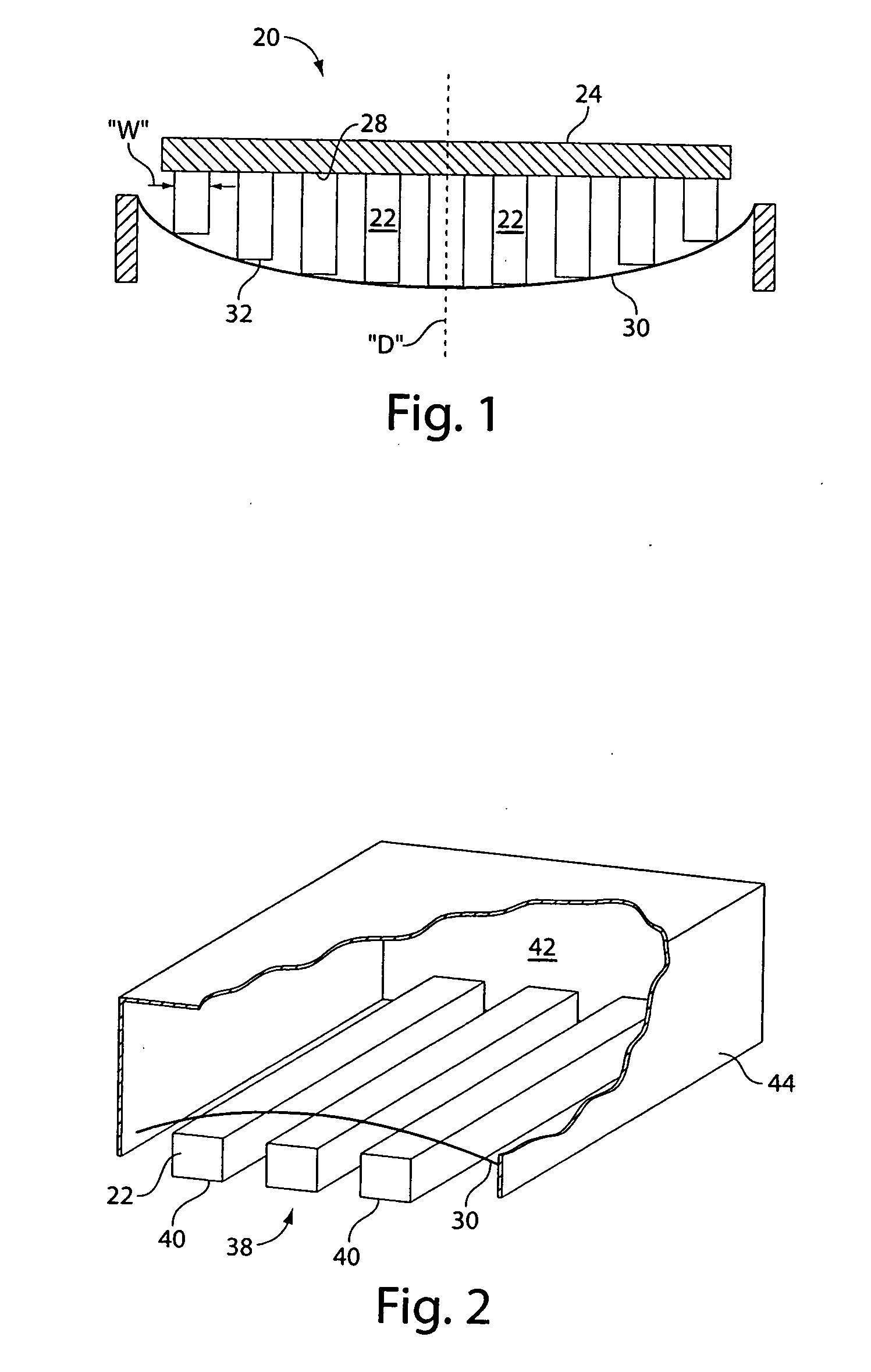
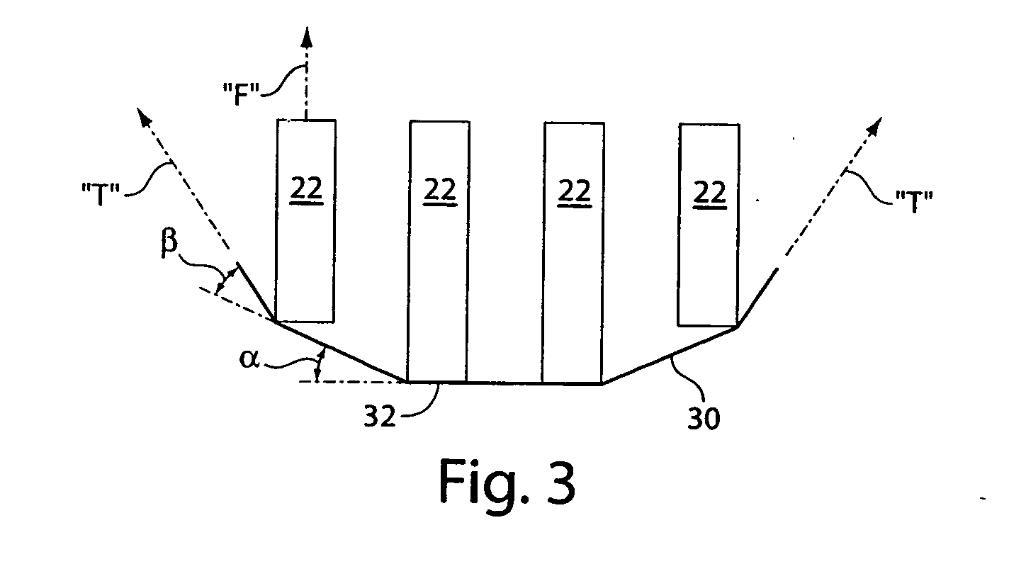
[0024] The electrical connectors of the present invention are adapted to provide an electrical connection with a mating surface, regardless of the shape of the mating surface. For example, connectors can be adapted to engage flat surfaces, concave surfaces, or other surfaces that lack portions extending from the mating surface toward the conductors. Connectors of many embodiments include a loading fiber and one or more electrical conductors. The connector is arranged, such that upon engagement with the mating surface, the conductor is displaced toward the loading fiber, thereby tensioning the loading fiber. Tensioning of the loading fiber, in turn, resists the movement of the conductors and in doing so, provides contact forces between the conductors and the mating surface.

[0025] Embodiments of the electrical connector allow materials with optimal electrical characteristics to be used as conductors, and materials with optimal mechanical properties to provide contact forces between t...


PUM

PropertyMeasurementUnit
electricalaaaaaaaaaa
contact forceaaaaaaaaaa
electrical connectionaaaaaaaaaa

Abstract

An electrical connector that has an array of conductors each having a contact point to make contact with a mating conductive surface. Upon engaging the contact points in a sliding manner with the mating surface, the conductors are displaced, which, in turn, tensions a loading fiber within the connector. Tensioning of the loading fiber provides a contact force between the contact points and the mating surface.

Description

[0001] This patent application claims priority to and is a continuation-in-part of pending U.S. patent application Ser. No. 10 / 985,322, filed Nov. 10, 2004, which is a continuation-in part of U.S. patent application Ser. No. 10 / 850,316, filed May 20, 2004 and now published under publication no. 2004-0214454 A1, which is a continuation-in-part of U.S. patent application Ser. No. 10 / 603,047, filed Jun. 24, 2003 and now published under publication no. US 2004-0005793 A1, which is a continuation-in-part of U.S. patent application Ser. No. 10 / 375,481, filed Feb. 27, 2003 and now published under publication no. US 2004-0048500 A1, which is a continuation-in-part of U.S. patent application Ser. No. 10 / 273,241, filed Oct. 17, 2002 and now published under publication no. US 2003-0134525 A1, which claims the benefit of U.S. provisional patent application Ser. No. 60 / 348,588 filed Jan. 15, 2002. Each of the above identified references are hereby incorporated by reference in their entirety.BACK...

Claims


Application Information

Patent Timeline
Patent Type & Authority Applications(United States)
IPC IPC(8): H01R12/00
CPCB05D3/067B05D7/546B05D7/576C09D5/34H01R12/714H01R13/22Y10T29/49155Y10T29/49117Y10T29/49124Y10T29/49105Y10T29/49119Y10T29/49162Y10S439/93
Inventor SWEETLAND, MATTHEW
Owner METHODE ELETRONICS INC
Why Eureka
Try Eureka