Ultrasound diagnosis apparatus

a technology of ultrasound and diagnostic equipment, applied in the field of ultrasound diagnostic equipment, can solve the problems of small error, large error, and often appearing artifacts in the doppler-mode and b-mode images

Inactive Publication Date: 2005-09-15
TOSHIBA MEDICAL SYST CORP
View PDF1 Cites 16 Cited by
  • Summary
  • Abstract
  • Description
  • Claims
  • Application Information

AI Technical Summary

Problems solved by technology

In addition, artifacts may often appear in the Doppler-mode images and the B-mode images because of echo signals remaining mutually between in the Doppler-mode and the B-mode.
When the body of the specimen is in a steady condition, the error is small while the error becomes large when the body is in an unsteady condition.
The large error leads to vertically-striped Doppler-mode (or spectrum) images resulting from an unsmooth connection be

Method used


Image

  • Ultrasound diagnosis apparatus
  • Ultrasound diagnosis apparatus
  • Ultrasound diagnosis apparatus

Examples


Embodiment Construction

[0025] Embodiments of the present invention will be described with reference to the accompanying drawings.

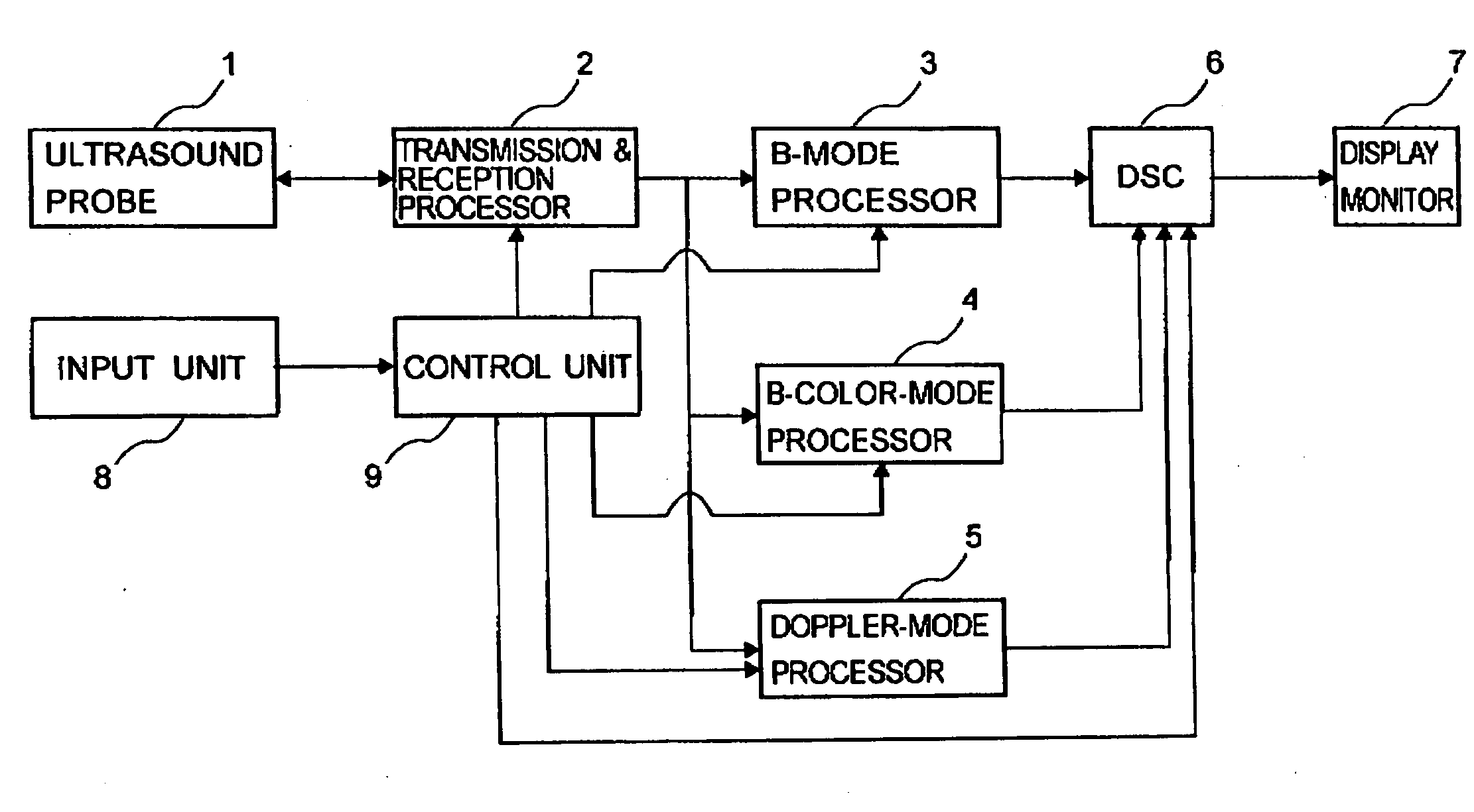
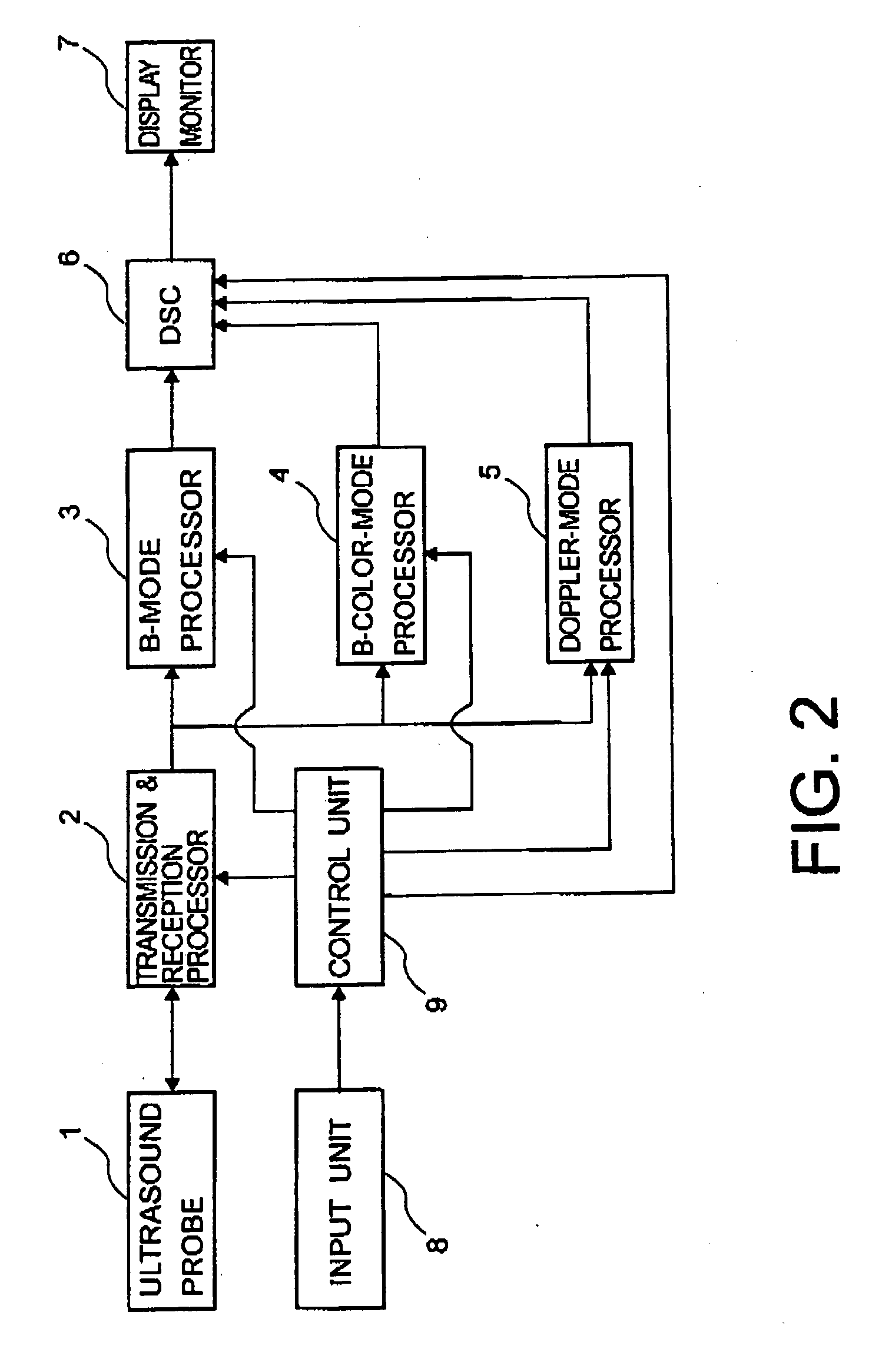
[0026]FIG. 2 is a block diagram showing an exemplary configuration of an ultrasound diagnosis apparatus. As shown in FIG. 2, the ultrasound diagnosis apparatus includes an ultrasound probe 1, a transmission and reception processor 2, a B-mode processor 3, a B-color-mode processor 4, a Doppler-mode processor 5, a digital scan converter (DSC) 6, a display monitor 7, an input unit 8, and a control unit 9.

[0027] The ultrasound probe 1 transmits ultrasound signals (waves, or pulses) to the specimen and receives echo signals from the specimen as ‘a scanner’. The echo signals result from the transmitted ultrasound signals which are reflected inside the body of the specimen. In other words, the ultrasound probe 1 electronically scans by transmitting the ultrasound signals towards a target area inside the specimen's body while the ultrasound probe 1 receives the echo signals from insid...


PUM


Abstract

An ultrasound diagnosis apparatus includes a scanner, an input unit, a change unit, a prediction unit, a processor, and a second processor. The scanner is configured to conduct an ultrasound segment scan by alternating a B-mode scan and a Doppler-mode scan. The input unit is configured to input an instruction. The change unit is configured to change a first period of the B-mode scan and a second period of the Doppler-mode scan in accordance with the instruction. The prediction unit is configured to predict a first Doppler signal with respect to the first period. The processor is configured to prepare an Doppler-mode image based on the first Doppler signal and a second Doppler signal resulting from the Doppler-mode scan. The second processor is configured to prepare a B-mode image based on a B-mode signal resulting from the B-mode scan.

Description

CROSS-REFERENCE TO RELATED APPLICATION [0001] This application is based upon and claims the benefit of priority from prior Japanese Patent Application No. P2003-409238, filed on Dec. 8, 2003, the entire contents of which are incorporated herein by reference. BACKGROUND OF THE INVENTION [0002] 1. Field of the Invention [0003] The present invention relates to an ultrasound diagnosis apparatus which prepares B-mode images and Doppler-mode images. The present invention also relates to a method of preparing B-mode images and Doppler-mode images. [0004] 2. Discussion of the Background [0005] In an ultrasound diagnosis apparatus, it is known to often display both Doppler-mode images (or Doppler spectrums) and B-mode images (or tomograms) of a specimen such as, for example, a patient substantially in real time. To accomplish such a display, two techniques shown in FIGS. 1A and 1B are known as its examples. FIG. 1A is an illustration for explaining one of the techniques which may be called a...

Claims


Application Information

Patent Timeline
IPC IPC(8): A61B8/00A61B8/12A61B8/14A61B8/06G01S7/52G01S15/89
CPCA61B8/06A61B8/13A61B8/463G01S15/8979G01S7/52074G01S7/52085A61B8/465
Inventor TAKIMOTO, MASAO
Owner TOSHIBA MEDICAL SYST CORP
Why Eureka
Try Eureka