Measurement probe and using method for the same

a measurement probe and optical technology, applied in the field of optical measuring probes, can solve the problems of difficult setting of the reflecting plane perpendicular to the measuring light beam, difficult to achieve high-accuracy measurement, and difficult to meet the measurement requirements of light beams, etc., to achieve convenient manufacturing, enhance measurement stability, and simplify the constitution

Inactive Publication Date: 2005-09-22
PANASONIC CORP
View PDF8 Cites 19 Cited by
  • Summary
  • Abstract
  • Description
  • Claims
  • Application Information

AI Technical Summary

Benefits of technology

[0012] An object of the present invention is to provide a measuring probe, which, compared to each of the described measuring probes, has a simplified constitution to facilitate manufacturing and is downsized to enhance stability of measurement, which further allows repla

Problems solved by technology

However, direct irradiation of the measuring target face with the measuring light beam makes high-accuracy measurement difficult due to reflection characteristics and influence of inclination of the measuring target face.
However, these conventional measuring probes have following problems.
Moreover, when the measuring probe is replaced, it is difficult to set the reflecting plane to be perpendicular to the measuring light beam.
Consequently, damages on the measuring target face or force acting in direction perpendicular to the measuring direction may cause failures of the springs or the contact portions of the measuring probes.
Moreover, in the case of the measuring probe disclosed in the Japanese publication of unexamined patent application No.
Further, as described above, the housing 101 serving as a fixed member is asse

Method used


Image

  • Measurement probe and using method for the same
  • Measurement probe and using method for the same
  • Measurement probe and using method for the same

Examples


Embodiment Construction

[0058] Hereinbelow, the embodiment of the present invention will be described in detail with reference to the drawings. It is to be noted that like parts are designated by like reference numerals throughout the accompanying drawings.

[0059] First, description is given of a measuring probe in one embodiment.

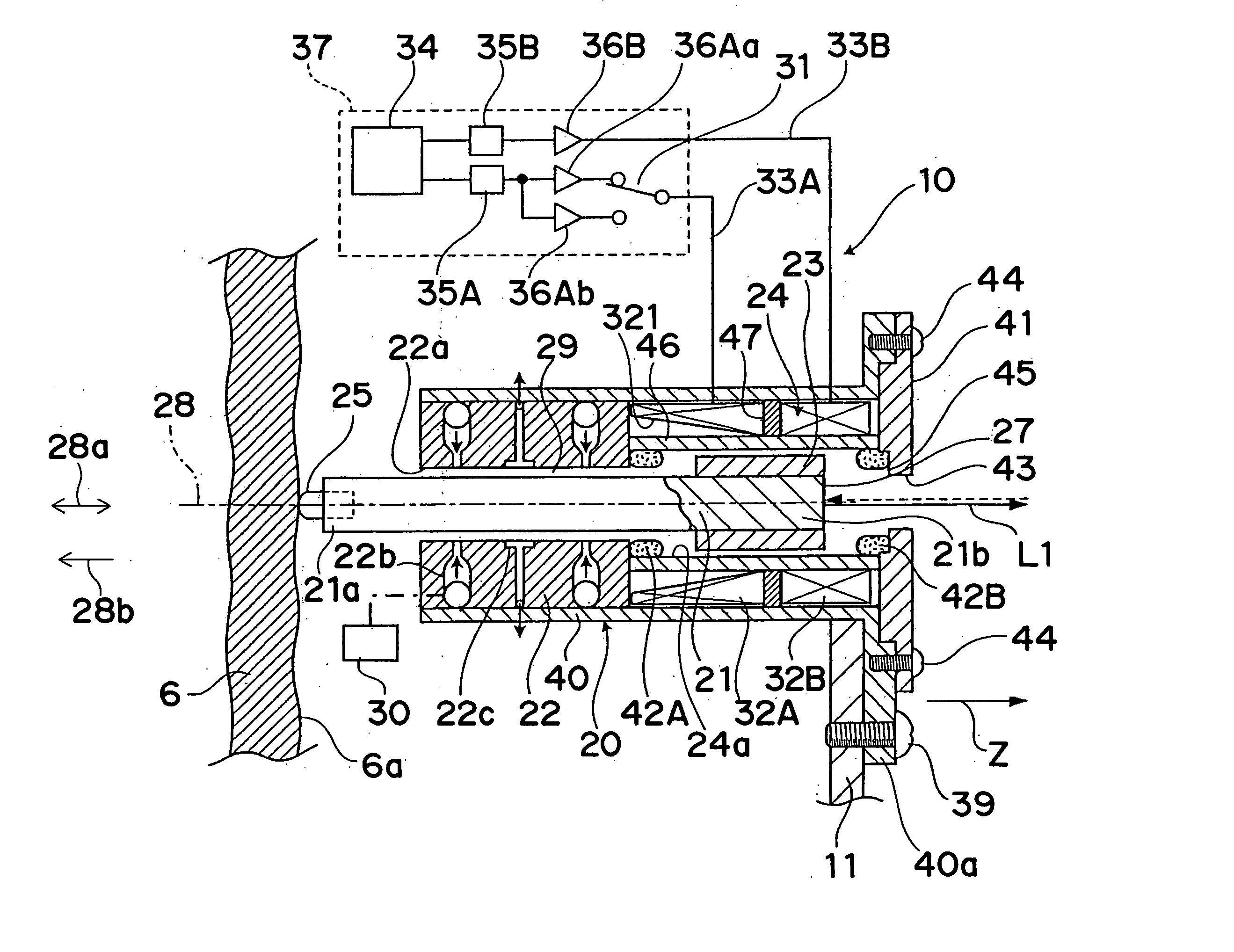
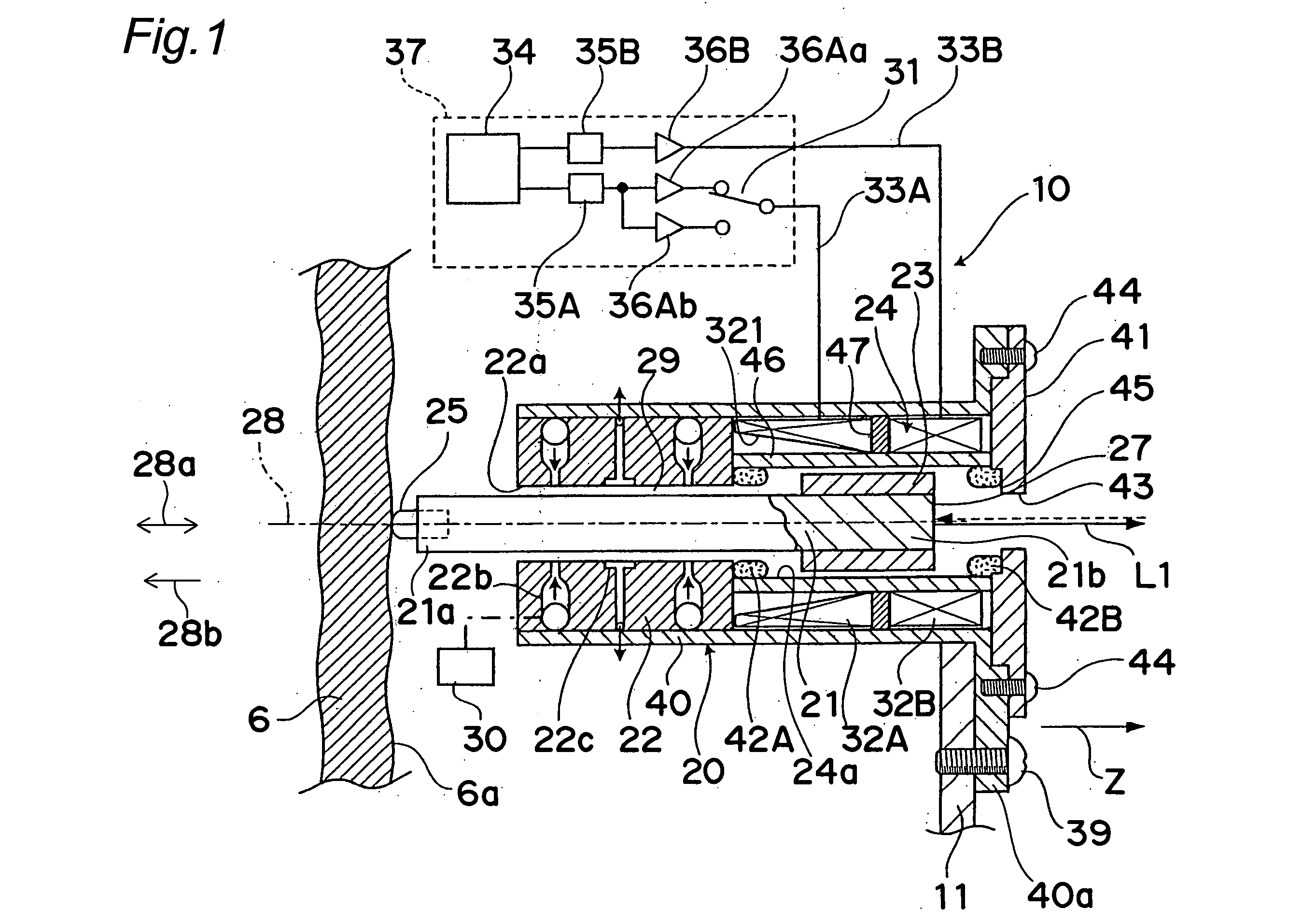
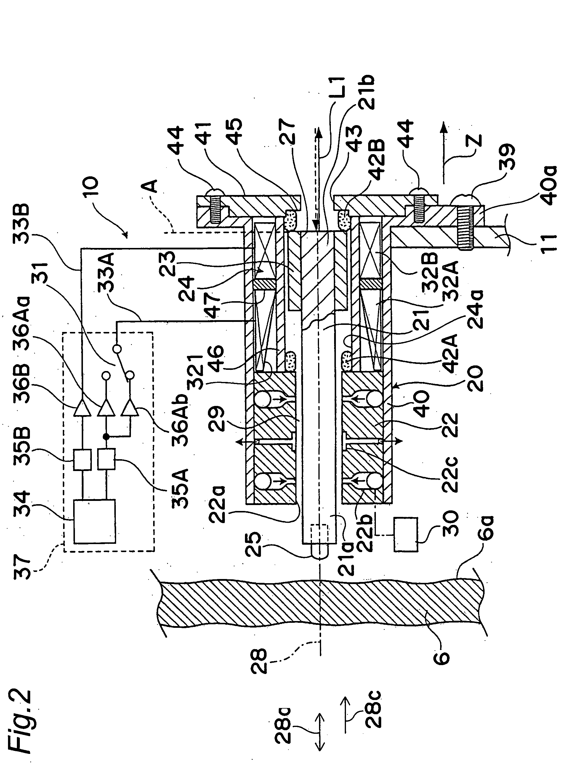
[0060]FIG. 1 shows a state in which a movable member 21 included in a measuring probe 10 according to one embodiment of the present invention is moved in a measuring direction 28b so as to bring a contact portion 25 into contact with a wafer 6 for obtaining information on a surface 6a of the wafer 6, i.e., measuring a position of the surface 6a or its changes. The wafer 6 is equivalent to one example of a measuring target object and the surface 6a of the wafer 6 is equivalent to one example of a measuring target face. FIG. 2 shows a state that the movable member 21 of the same measuring probe 10 is moved in a retreat direction 28c so as to place the contact portion 25 away from t...


PUM


Abstract

A measuring probe for obtaining positional information on a measuring target face has: a movable member having a contact portion which is formed in its top and comes into contact with the measuring target face and a reflecting plane formed on its base end for reflecting a measuring light beam; a magnetic substance mounted on the movable member; a fixed member disposed in a fixed state; a bearing provided on the fixed member for supporting the movable member movably in axis line direction; and a magnetic force generating portion provided on the fixed member for generating force acting upon the magnetic substance to move the movable member in the axis line direction. The movable member is formed from a nonmagnetic material, and the bearing and the fixed member are formed from a magnetic material.

Description

TECHNICAL FIELD [0001] The present invention relates to an optical measuring probe for obtaining positional information on a measuring target face, and to a method for using the measuring probe. BACKGROUND OF THE INVENTION [0002] An optical measuring apparatus irradiates a measuring target face with a measuring light beam and receives the measuring light beam reflected by the measuring target face so as to obtain information about displacement and shape of the measuring target face contained in the reflected measuring light beam. However, direct irradiation of the measuring target face with the measuring light beam makes high-accuracy measurement difficult due to reflection characteristics and influence of inclination of the measuring target face. Accordingly, various measuring probes having a function to move in conformity to the measuring target face and a function to reflect the measuring light beam have conventionally been proposed. [0003] For example, in Japanese publication of...

Claims


Application Information

Patent Timeline
IPC IPC(8): G01B3/00G01B21/00G01B5/00G01B5/012G01B7/00
CPCG01B3/008G01B7/002G01B5/012
Inventor KASSAI, TAKAAKIKUBO, KEISHIDOI, MASATERUMOCHIZUKI, HIROYUKIYOSIZUMI, KEIICHI
Owner PANASONIC CORP
Why Eureka
Try Eureka