Impact resistant shingle

a technology of impact resistance and shingle, which is applied in the field of shingle art, can solve the problems of cracks that can develop on the lower surface of the shingle, and achieve the effect of resisting cracking and dissipating mechanical energy

Inactive Publication Date: 2005-09-22
CERTAINTEED CORP
View PDF34 Cites 104 Cited by
  • Summary
  • Abstract
  • Description
  • Claims
  • Application Information

AI Technical Summary

Benefits of technology

[0005] The present invention is directed to an impact resistant shingle, in which an asphaltic material impregnates the base mat of the shingle and the upper surface of the shingle, but wherein an additional layer of a modified asphaltic material, having greater ability to resist cracking than that of the principal asphaltic material and being softer than the principal asphaltic material, is provided, such that the softer asphaltic material is on the rear surface of the shingle that faces the roof on which the shingle is to be applied. When impacts from hail stones, tree branches, walking, or any other impacts are applied against an upper surface of a shingle that is installed on the roof, the softer asphaltic material on the rear surface of the shingle provides a means for dissipating at least some of the impact, whereby crack formation on the lower surface of the shingle is avoided. The modified asphaltic material should have the ability to dissipate mechanical energy. A polymer modified asphalt can have such ability, such that it can resist cracking because it yields or flexes when sharply struck, rather than fracturing.
[0006] Accordingly, it is a primary object of this invention to provide a shingle having a softer, impact-resistant layer of modified asphaltic material on its lower surface, that has a greater ability to resist cracking and a greater ability to dissipate energy under conditions in which the upper surface of the shingle is subjected to impact, than the other asphaltic material that is used in the manufacture of the shingle.

Problems solved by technology

It has been found that when shingles that have been installed on a roof are subjected to various kinds of impacts, such as falling tree branches, workman walking on the shingles, or hail stones striking the shingles, especially during cold weather conditions, cracks can develop in the lower surface of the shingle as a result of such impacts.

Method used


Image

  • Impact resistant shingle
  • Impact resistant shingle
  • Impact resistant shingle

Examples


Embodiment Construction

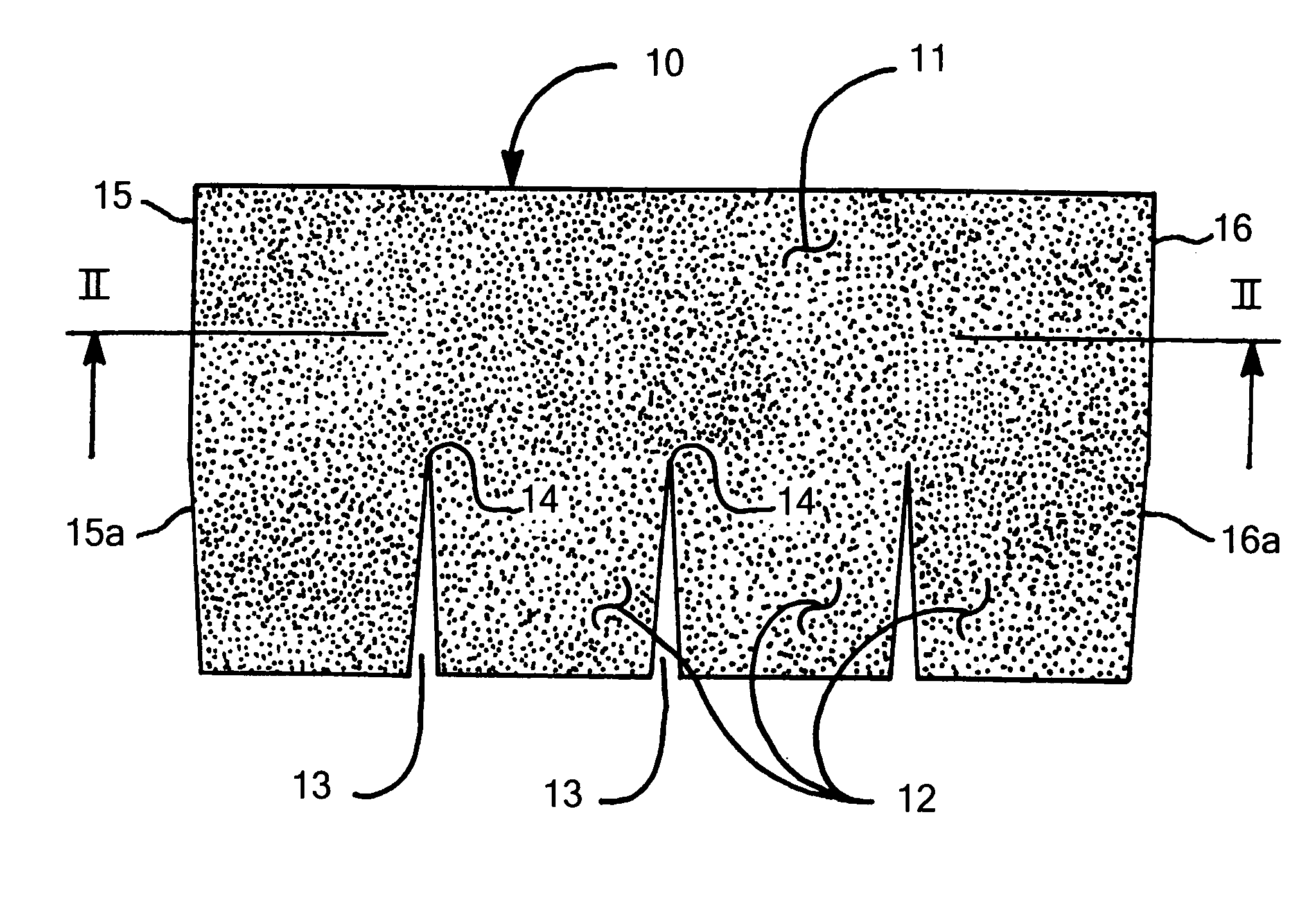
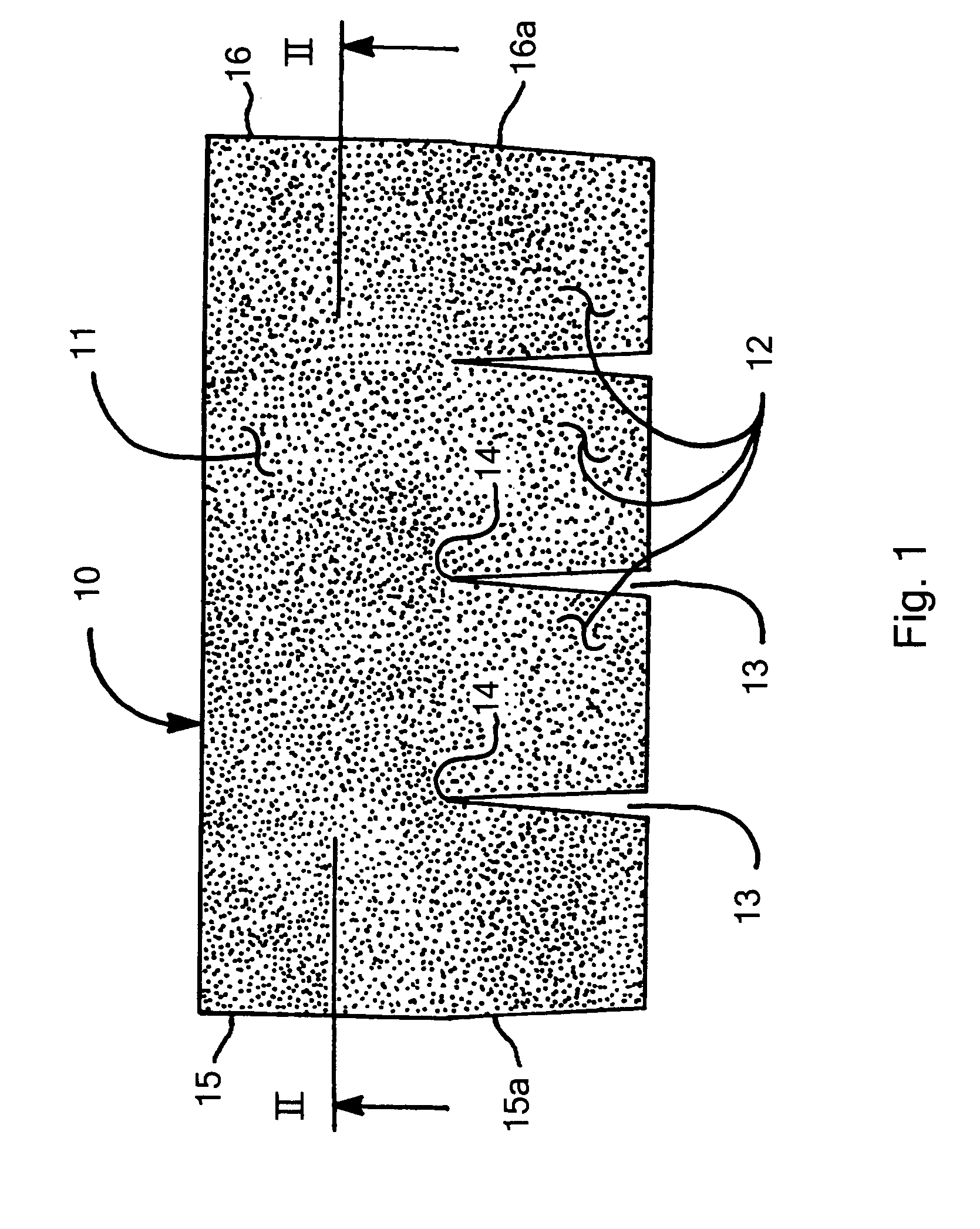
[0023] Referring now to the drawings in detail, reference is first made to FIG. 1, wherein a shingle is shown, generally designated by the numeral 10. The shingle 10 is comprised of an upper headlap portion 11 and lower tab portions 12, with the tab portions being four in number. The various tab portions 12 are spaced apart by slotted openings 13.

[0024] The upper headlap portion 11 is that which is disposed above the upper ends of the slotted openings 14. Left and right edges 15 and 16, respectively, of the shingle 10 have partial cut-outs 15a and 16a, respectively, such that when shingles 10 are aligned left-to-right, portions of slotted openings 15a and 16a will come together forming full slotted openings.

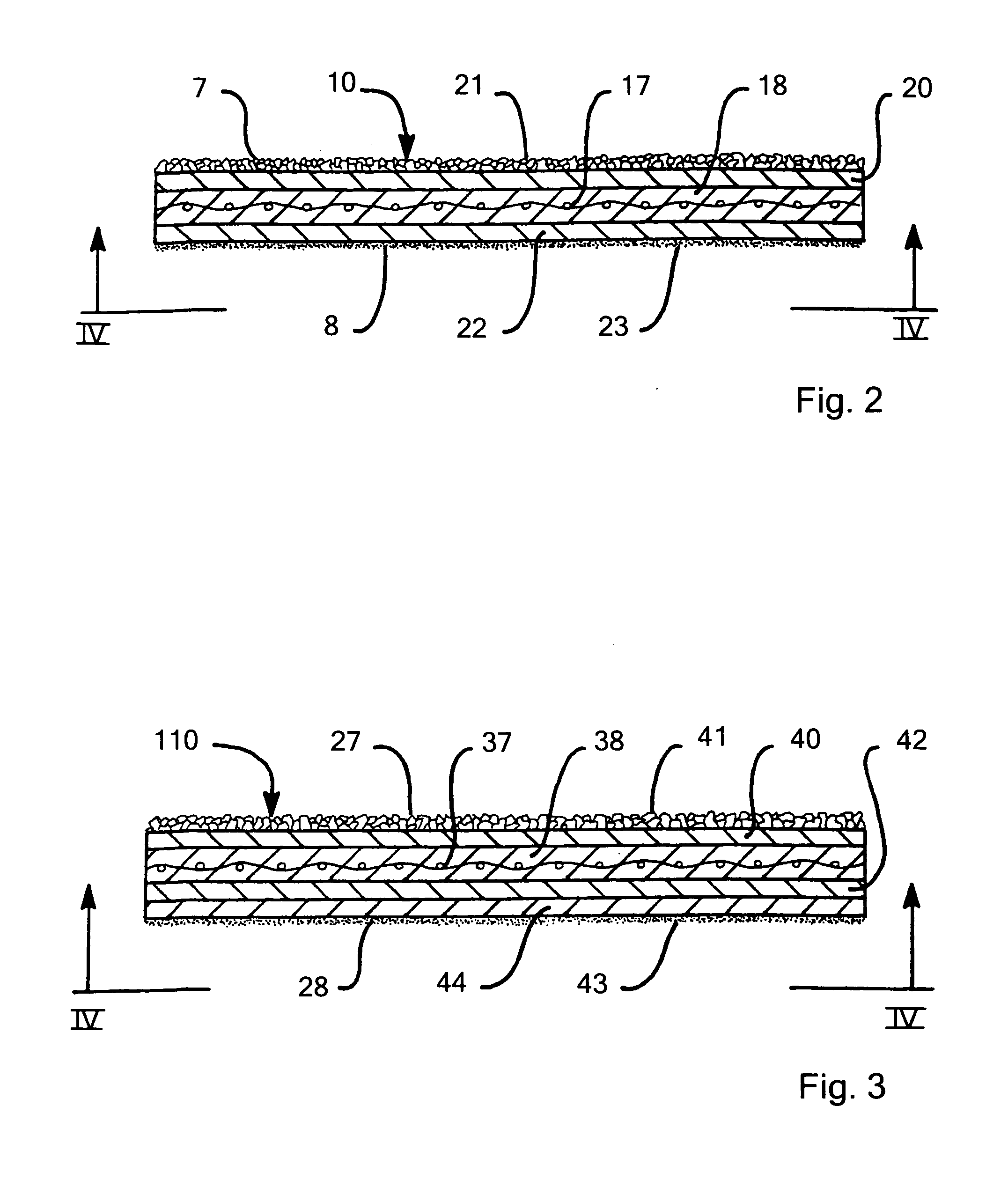
[0025] With reference to the shingle of FIGS. 2 and 2A, the shingle 10 has respective upper and lower surfaces 7, 8 and is comprised of a base mat 17 of preferably fiberglass mat construction, although the same can be comprised of organic mat, or fibered polymeric mat construct...


PUM

PropertyMeasurementUnit
elongation at breakaaaaaaaaaa
softening pointaaaaaaaaaa

Abstract

An impact resistant shingle is provided, wherein the base mat is impregnated with an asphaltic material, with an asphaltic material on the upper surface of the shingle, and wherein another asphaltic material is disposed on the rear surface of the shingle, which other asphaltic material is softer with greater elongation than the asphaltic material used elsewhere in the shingle, such that crack resistance is afforded because energy from impact on the shingle is dissipated.

Description

CROSS-REFERENCE TO RELATED APPLICATIONS [0001] This is a continuation-in-part of U.S. application Ser. No. 10 / 871,911, filed Jun. 18, 2004, which in turn is a continuation of Ser. No. 10 / 288,747, filed Nov. 6, 2002, the complete disclosures both of which is herein incorporated by reference.BACKGROUND OF THE INVENTION [0002] It is known in the shingle art that today's shingles are generally made of a base mat of fibrous construction, most usually of fiberglass construction, that is impregnated with an asphaltic material. The asphaltic material, generally bitumen, of some formulation is disposed on the upper surface of the base mat, and serves to adhere a layer of mineral granules into the asphaltic material on the upper surface of the base mat. Generally such occurs over the entirety of the upper surface of the shingle, but, such mineral granules can, if desired, be applied only to a visible portion of the upper surface of the shingle, to be visible in the installed condition, and to...

Claims


Application Information

Patent Timeline
Patent Type & Authority Applications(United States)
IPC IPC(8): B32B11/02E04D1/00E04D1/26
CPCB32B11/02B32B2395/00Y10T428/24372E04D2001/005E04D1/26B32B11/04B32B11/12B32B2260/021B32B2260/042B32B2419/06
Inventor SNYDER, RICHARD ALLANKALKANOGLU, HUSNU M.JACOBS, GREGORY F.
Owner CERTAINTEED CORP
Why Eureka
Try Eureka