Methods and systems for using RFID in biological field

Active Publication Date: 2005-09-22
APPL BIOSYSTEMS INC
View PDF56 Cites 133 Cited by
  • Summary
  • Abstract
  • Description
  • Claims
  • Application Information

AI Technical Summary

Problems solved by technology

To read a label or a barcode, however, requires an optical path to the barcode, which can be inconvenient and problematic, for example if the indicia to be read are located inside of an instrument.
Such windows can complicate the design of instruments and carriers and depending on the configuration and design of a particular window, the optical path can be distorted, resulting in optical reading and scanning problems.
Further reading problems can result from printing inconsistencies and any material that covers the bar code, such as

Method used


Image

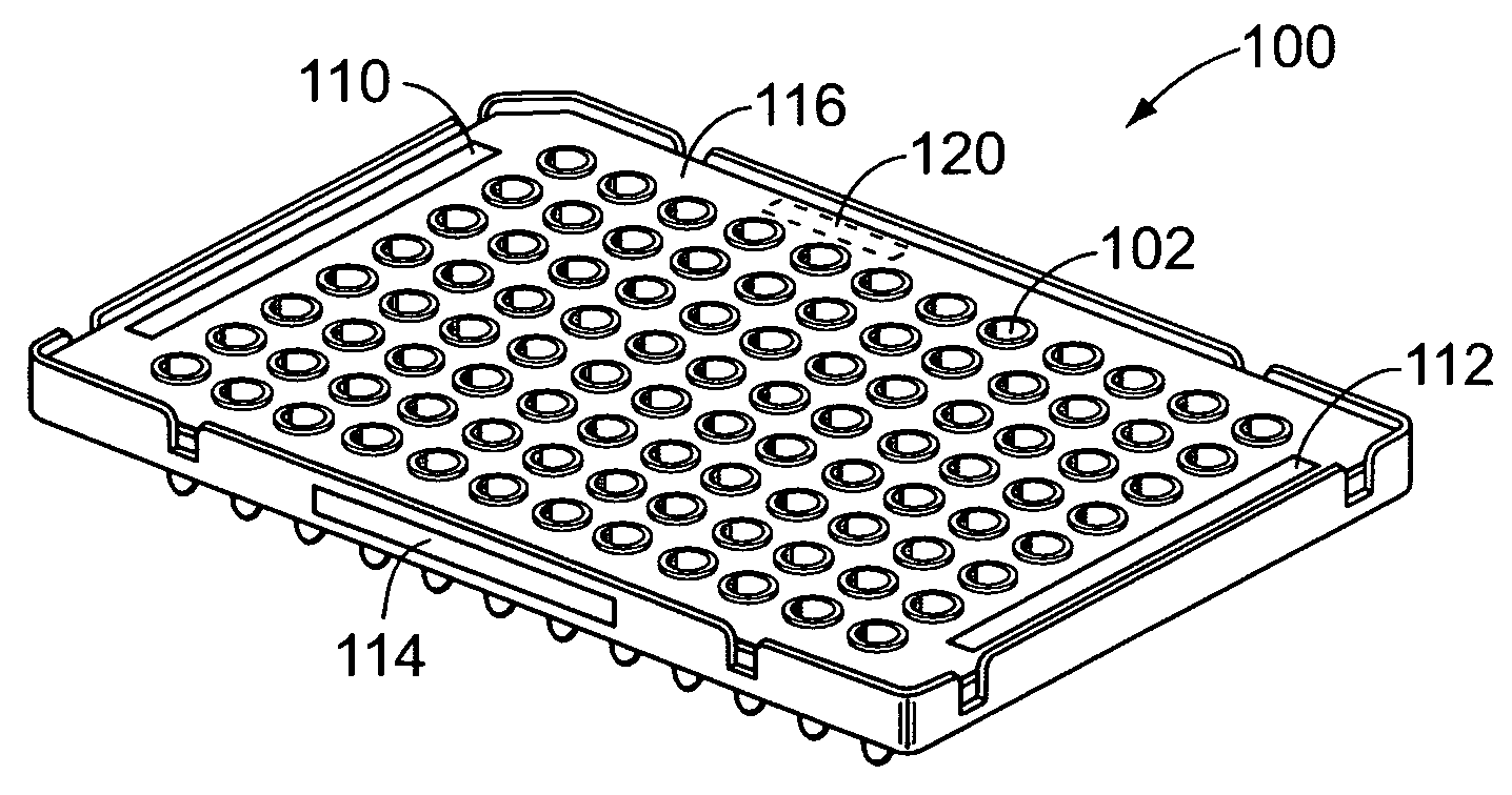
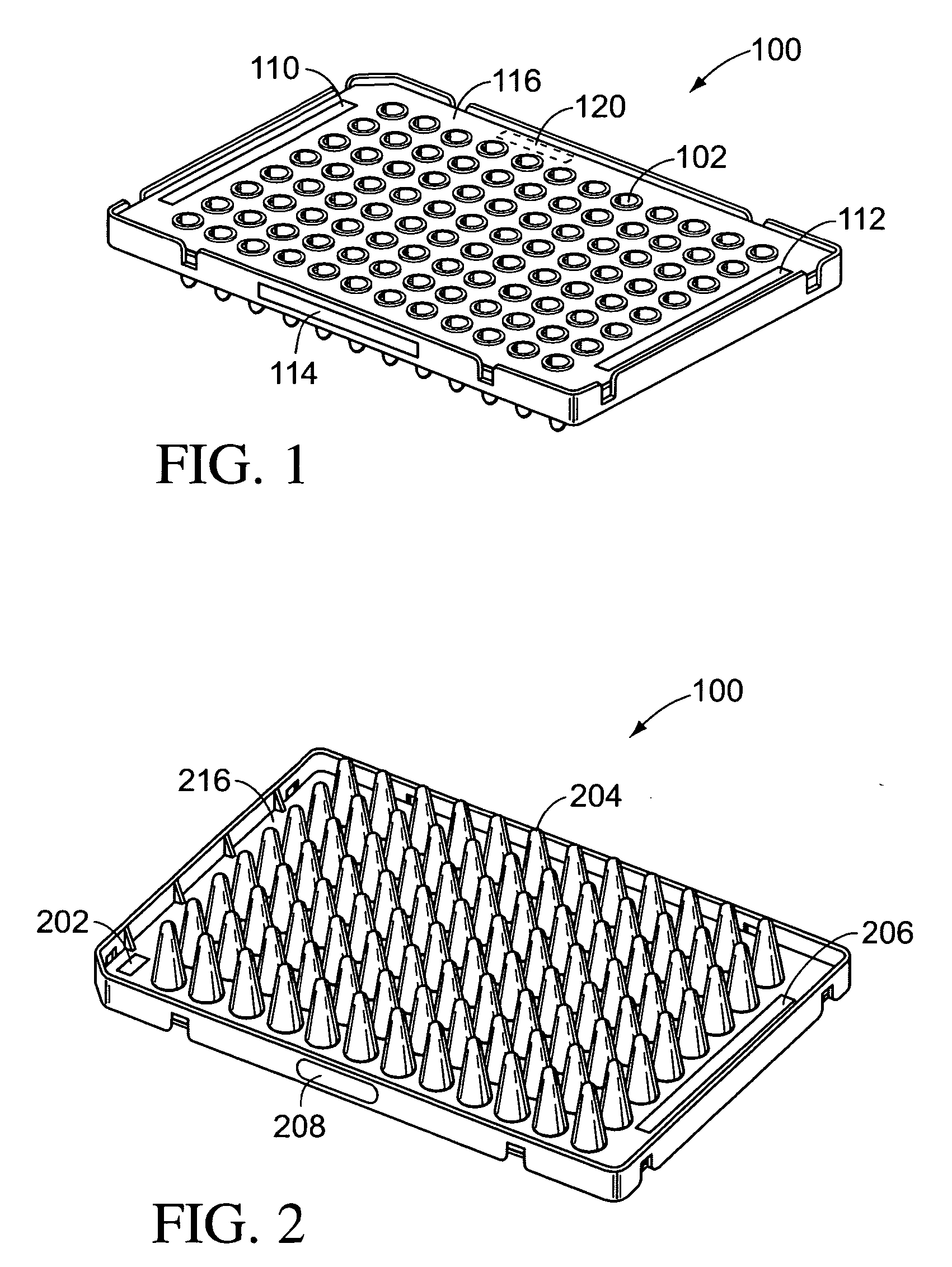
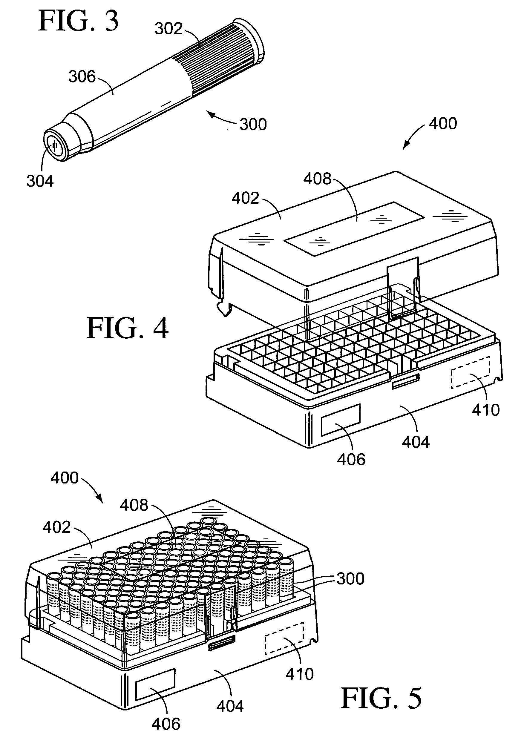
  • Methods and systems for using RFID in biological field
  • Methods and systems for using RFID in biological field
  • Methods and systems for using RFID in biological field

Examples


Embodiment Construction

[0027] Reference will now be made in detail to some embodiments, examples of which are illustrated in the accompanying drawings. Wherever possible, the same reference numbers are used throughout the drawings to refer to the same or like parts.

[0028] Radio Frequency Identification (“RFID”) provides a convenient mechanism for identifying and detecting objects using wireless electromagnetic signals. A basic RFID system has at least one RFID reader and at least one RFID tag. Typically, RFID readers can include a coil or antenna and circuitry to transmit and receive signals with the coil or antenna. An RFID tag also includes a coil or antenna and some information that can be read by an RFID reader.

[0029] The RFID reader antenna generates an electromagnetic field, thereby transferring energy to the tag. Depending on the design of the tag, a portion of the energy transferred to the tag will be reflected to the reader so as to provide information about the tag back to the reader. Some RFI...


PUM


Abstract

Biological reagent carrier devices and methods are disclosed, which employ RFID techniques to associate information with biological reagents.

Description

INTRODUCTION [0001] The present teaching relates to methods and systems for associating information with carriers for supporting biological reagents. During the manufacture and use of biological reagents, the reagents are typically coded and labeled in order to keep track of them. Conventional systems use bar codes to identify carriers containing reagents to be processed by analytical instrumentation. Bar codes, however, require printing and application of a bar code label to carriers for the biological reagents. At some later time the bar code is read by either a hand-held bar code scanner or by an automated bar-code scanner controlled by the instrumentation to track the reagents as they are processed. [0002] To read a label or a barcode, however, requires an optical path to the barcode, which can be inconvenient and problematic, for example if the indicia to be read are located inside of an instrument. In the past these problems have been addressed by forming windows in the instru...

Claims


Application Information

Patent Timeline
IPC IPC(8): B01L3/00B01L3/14B01L9/06G01N1/02G01N35/00G06Q10/00G08B13/14
CPCB01L3/5027G06K7/10366B01L3/5085B01L3/545B01L9/06B01L2300/022G01N35/00732G01N2001/021G01N2035/00782G06Q10/087G08C17/02B01L3/527G06K7/0008G06K19/07749B01L2300/021B01L3/5082B01L3/5453B01L2300/0816B01L2300/0819B01L2300/0832
Inventor MORRIS, RICHARD D.MACK, JEROME A.
Owner APPL BIOSYSTEMS INC
Why Eureka
Try Eureka