
Defferential-fed stacked patch antenna

a patch antenna and differential feeding technology, applied in the field of antennas, can solve the problems of ripple in the pattern peak, not suitable for spherical scanning antenna test systems, and requires frequent changing of probe antennas

Active Publication Date: 2005-09-22
GOOGLE TECH HLDG LLC
View PDF12 Cites 72 Cited by
  • Summary
  • Abstract
  • Description
  • Claims
  • Application Information

AI Technical Summary

Problems solved by technology

One challenge to antenna testing system designers is meeting the CTIA requirements while maintaining moderate range distances and ceiling heights.
Wideband horn antennas tend to change modes of operation over their range of frequencies and are thus not suitable for spherical-scanning antenna test systems.
This is inconvenient and requires frequent changing of the probe antenna.
The high-frequency element is also more susceptible to diffraction / reflection effects from the low-frequency ground plane, which cause ripple in the pattern peak.
This increases the difficulty required to satisfy the CTIA requirements.

Method used


Image

  • Defferential-fed stacked patch antenna
  • Defferential-fed stacked patch antenna
  • Defferential-fed stacked patch antenna

Examples


Embodiment Construction

[0013] As required, detailed embodiments of the present invention are disclosed herein; however, it is to be understood that the disclosed embodiments are merely exemplary of the invention, which can be embodied in various forms. Therefore, specific structural and functional details disclosed herein are not to be interpreted as limiting, but merely as a basis for the claims and as a representative basis for teaching one skilled in the art to variously employ the present invention in virtually any appropriately detailed structure. Further, the terms and phrases used herein are not intended to be limiting; but rather, to provide an understandable description of the invention.

[0014] The terms a or an, as used herein, are defined as one or more than one. The term plurality, as used herein, is defined as two or more than two. The term another, as used herein, is defined as at least a second or more. The terms including and / or having, as used herein, are defined as comprising (i.e., open...


PUM


Abstract

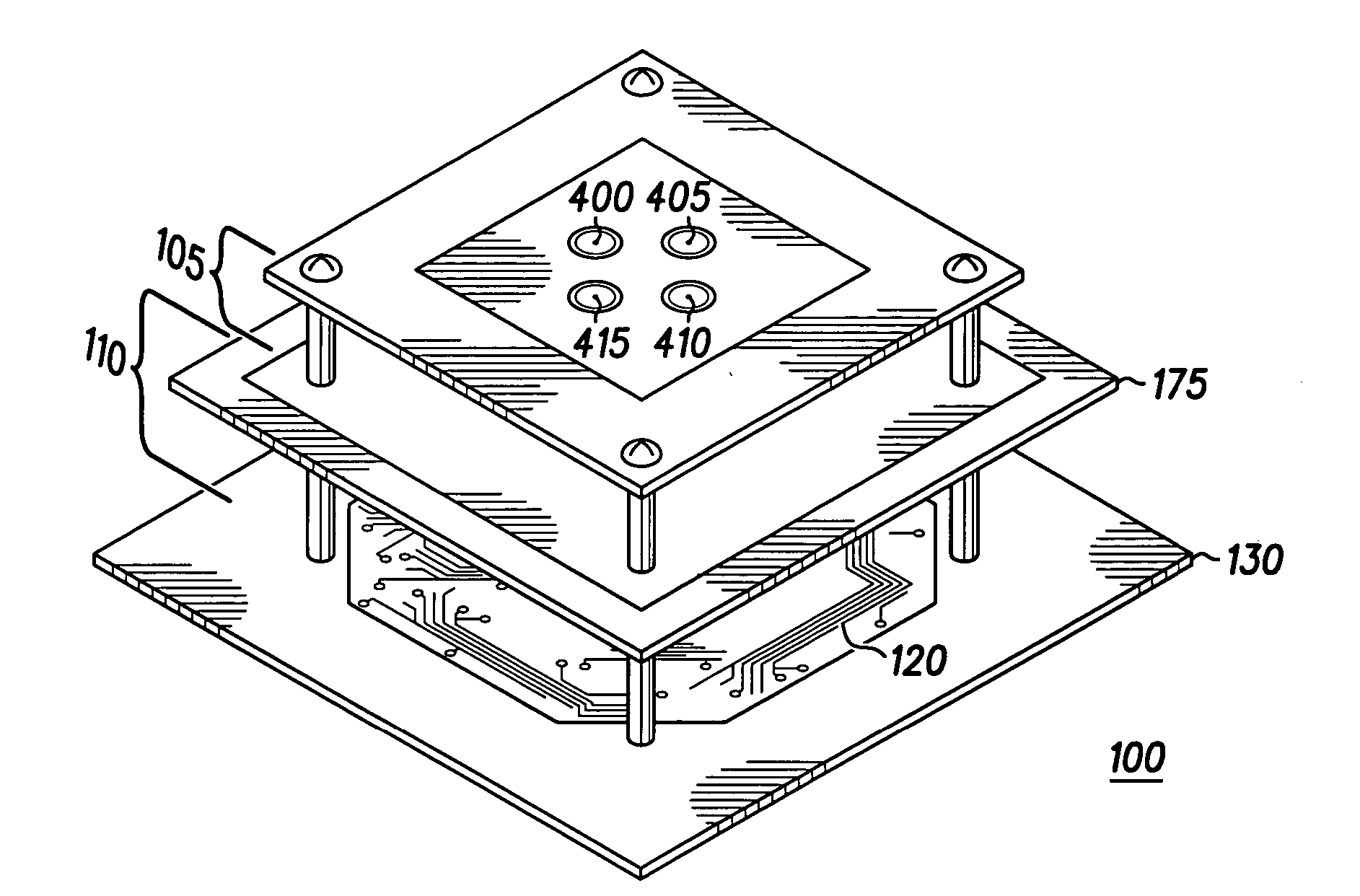
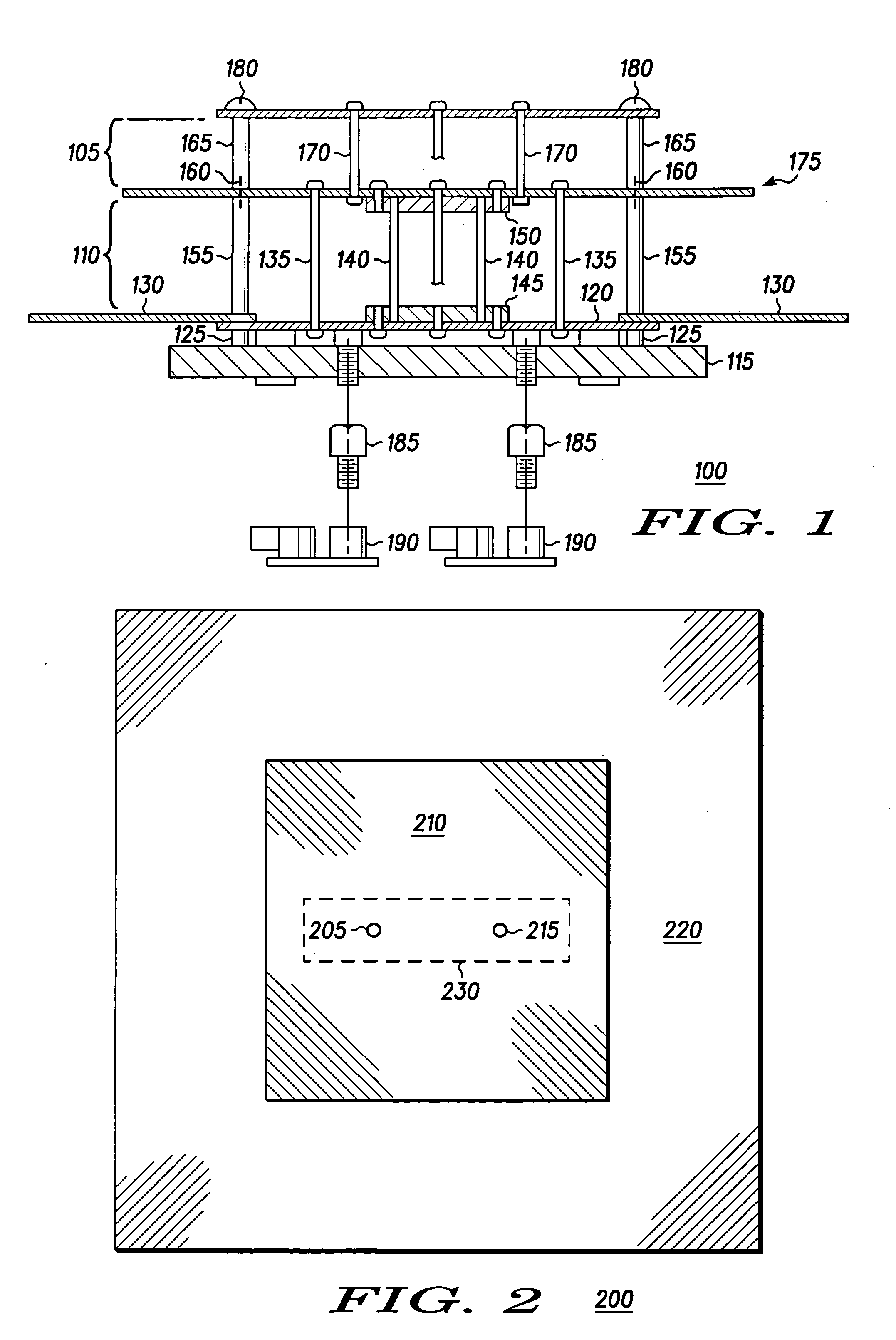
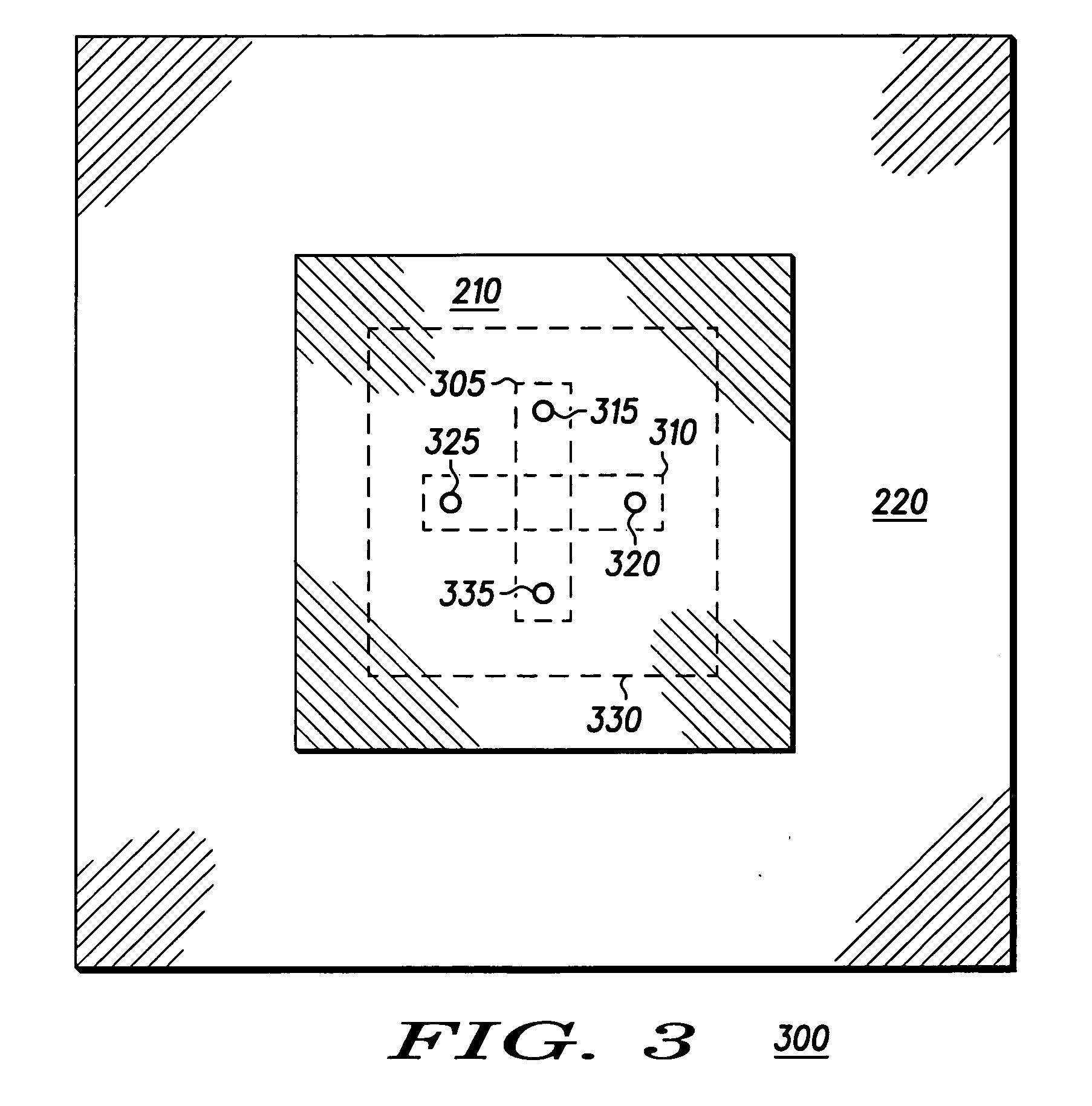
An antenna system includes a stacked patch antenna (100) comprising two or more patch antennas symmetrically aligned around an axis. The stacked patch antenna (100) comprises a differential feed patch antenna. The two or more patch antennas include a first patch antenna (105) and a second patch antenna (110). At least a portion of the second patch antenna (110) serves as a ground plane for the first patch antenna (105).

Description

BACKGROUND OF THE INVENTION [0001] 1. Field of the Invention [0002] The present invention is generally related to antennas and more particularly to an antenna for use in an antenna test system. [0003] 2. Description of the Related Art [0004] The Cellular Telecommunications and Internet Association (CTIA) operates an equipment testing and certification program to ensure high-quality and reliability of cellular, personal communication services enhanced specialized mobile radio, and mobile satellite services. Included within this program, CTIA establishes requirements for spherical-scanning antenna measurement systems (i.e. anechoic chambers). One challenge to antenna testing system designers is meeting the CTIA requirements while maintaining moderate range distances and ceiling heights. To do so efficiently, a measurement antenna that is low profile, dual-polarized, and multi-band is desired. The antenna preferably has a directive radiation pattern with high symmetry and low taper acr...

Claims


Application Information

Patent Timeline
Patent Type & Authority Applications(United States)
IPC IPC(8): H01Q1/38H01Q5/00H01Q5/40H01Q9/04
CPCH01Q9/0414H01Q5/40H01Q9/0435
Inventor PHILLIPS, JAMES P.KRENZ, ERIC L.REICH, PAUL W.
Owner GOOGLE TECH HLDG LLC
Learn More