Method and apparatus for generating a shadow effect using shadow volumes

a technology of shadow volume and shadow volume, applied in the field of computer graphics systems, can solve the problems of inefficient stencil operation, high memory bandwidth, and high time consumption of ray tracing techniques, and achieve significant memory bandwidth inefficiencies

Active Publication Date: 2005-09-22
VIA TECH INC
View PDF6 Cites 50 Cited by
  • Summary
  • Abstract
  • Description
  • Claims
  • Application Information

AI Technical Summary

Benefits of technology

[0021] Other embodiments of the present invention are directed to methods for generating a shadow effect in a computer graphics system. In this regard, one embodiment of such a method, among others, performs the stencil shadow volume method using a compressed stencil buffer where the compressed stencil

Problems solved by technology

Since the ray tracing technique is very time consuming, especially with multiple occluders and multiple light sources, the stencil shadow volume method simplifies the operation by performing a simple in/out counting method using the stencil buffer.
Although computer graphics pr

Method used


Image

  • Method and apparatus for generating a shadow effect using shadow volumes
  • Method and apparatus for generating a shadow effect using shadow volumes
  • Method and apparatus for generating a shadow effect using shadow volumes

Examples


Embodiment Construction

[0040] Having summarized various aspects of the present invention, reference will now be made in detail to the description of the invention as illustrated in the drawings. While the invention will be described in connection with these drawings, there is no intent to limit it to the embodiment or embodiments disclosed therein. On the contrary, the intent is to cover all alternatives, modifications and equivalents included within the spirit and scope of the invention as defined by the appended claims.

[0041] It is noted that the drawings presented herein have been provided to illustrate certain features and aspects of embodiments of the invention. It will be appreciated from the description provided herein that a variety of alternative embodiments and implementations may be realized, consistent with the scope and spirit of the present invention.

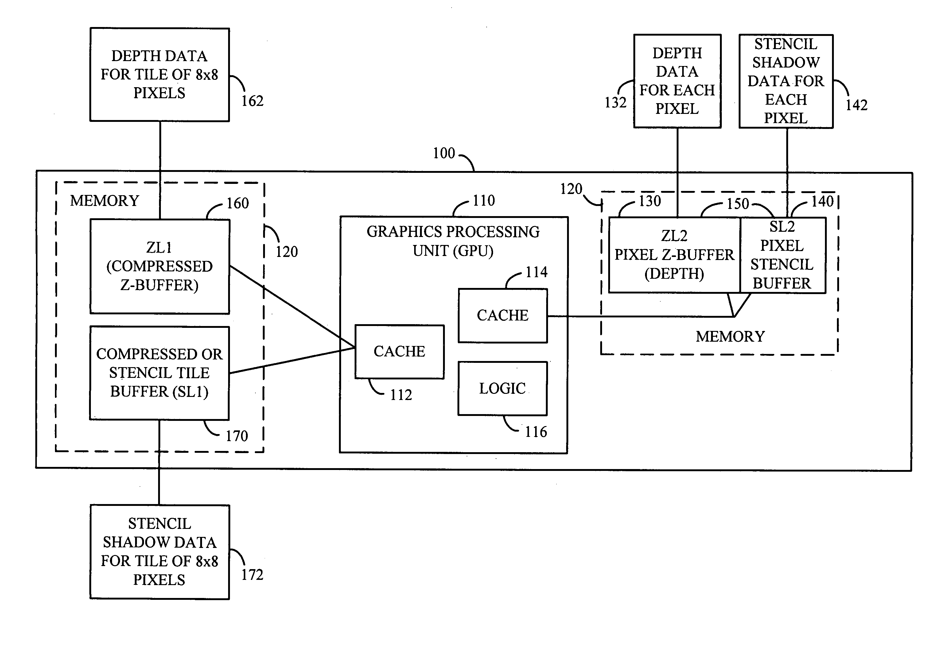
[0042] As summarized above, the present application is directed to embodiments of apparatus, systems and methods of generating a shadow effec...


PUM


Abstract

The computer graphics system is configured to generate a shadow effect with a stencil shadow volume method using a combination of compressed and uncompressed stencil buffers in coordination with compressed and uncompressed depth data buffers. An uncompressed stencil buffer is capable of storing stencil shadow volume data for each pixel and a compressed stencil buffer is capable of storing stencil shadow volume data for a group of pixels.

Description

FIELD OF THE INVENTION [0001] The present invention generally relates to computer graphics systems, and more particularly to a method and apparatus for generating a shadow effect using a shadow volumes approach. BACKGROUND OF THE INVENTION [0002] As is known, the art and science of three-dimensional (“3-D”) computer graphics concerns the generation, or rendering, of two-dimensional (“2-D”) images of 3-D objects for display or presentation onto a display device or monitor, such as a Cathode Ray Tube (CRT) or a Liquid Crystal Display (LCD). The object may be a simple geometry primitive such as a point, a line segment, a triangle, or a polygon. More complex objects can be rendered onto a display device by representing the objects with a series of connected planar polygons, such as, for example, by representing the objects as a series of connected planar triangles. All geometry primitives may eventually be described in terms of one vertex or a set of vertices, for example, coordinate (x...

Claims


Application Information

Patent Timeline
IPC IPC(8): G06F13/00G06T15/00G06T15/60
CPCG06T15/60G06T15/005
Inventor XU, JIANGMINGCHEN, WEN-CHUNGWANG, YUANFENGLI, LIANGBROTHERS, JOHNPROKOPENKO, BORIS
Owner VIA TECH INC
Why Eureka
Try Eureka