
Image processing system, method of controlling the image processing system and control program for the image processing system

Inactive Publication Date: 2005-09-22
CANON KK
View PDF11 Cites 12 Cited by
  • Summary
  • Abstract
  • Description
  • Claims
  • Application Information

AI Technical Summary

Benefits of technology

[0030] It is an object of the present invention to provide an image processing system for enabling an image forming apparatus produced by a manufacturer to be used as far as possible by a user.
[0033] According to the present invention, design is made such that by the utilization of a user interface for controlling a recording process, a manufacturer or a vendor can appeal the predominance, particularly economy of their image forming apparatuses and therefore, they can have their image forming apparatuses used as far as possible by the user.

Problems solved by technology

In the future, however, unless any maker can provide information / environment / apparatus more attractable to the user, there comes out the possibility that even if the manufacturer supplies them, they will not be utilized.
On the other hand, when viewed from the technical side of the image forming apparatuses, the situation is such that an extreme discrimination in quality among the apparatuses cannot be made, and a distinction in the above-mentioned “reliability” and “performance” has become difficult to make.
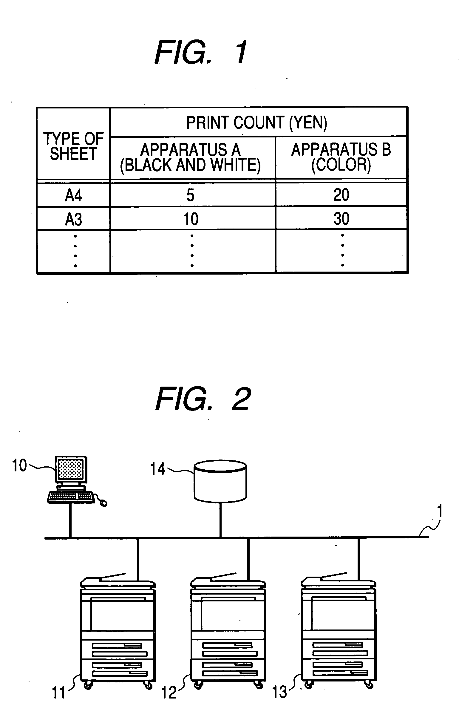
Regarding the “unit cost” as the remaining distinction item, as shown in FIG. 1, the price is determined by the cost when the apparatus is used as a single unit, and again in this item, the situation is such that a distinction is difficult to make.
It is disadvantageous to makers that the distinction is difficult to make as described above.

Method used


Image

  • Image processing system, method of controlling the image processing system and control program for the image processing system
  • Image processing system, method of controlling the image processing system and control program for the image processing system
  • Image processing system, method of controlling the image processing system and control program for the image processing system

Examples


first embodiment

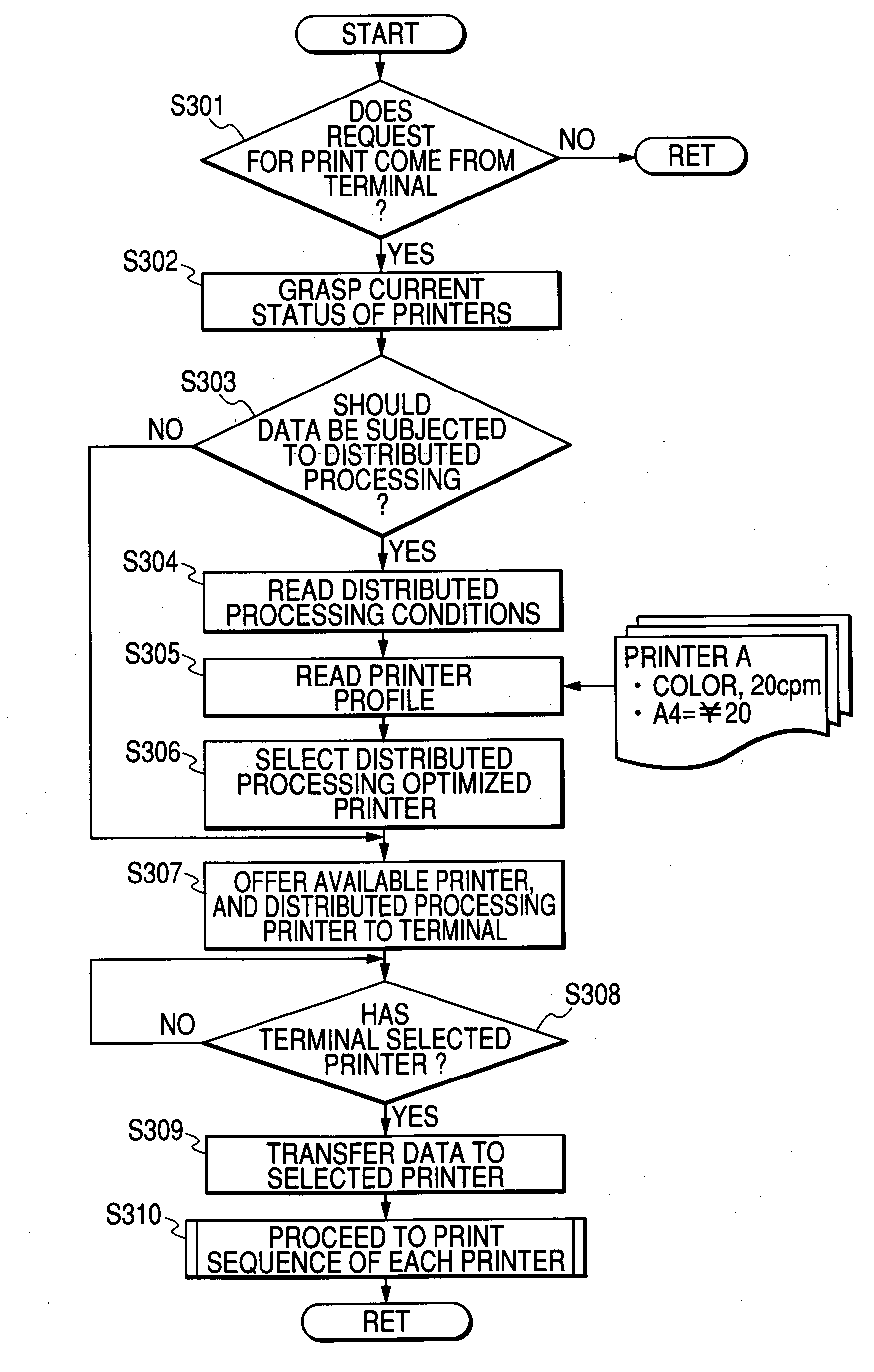
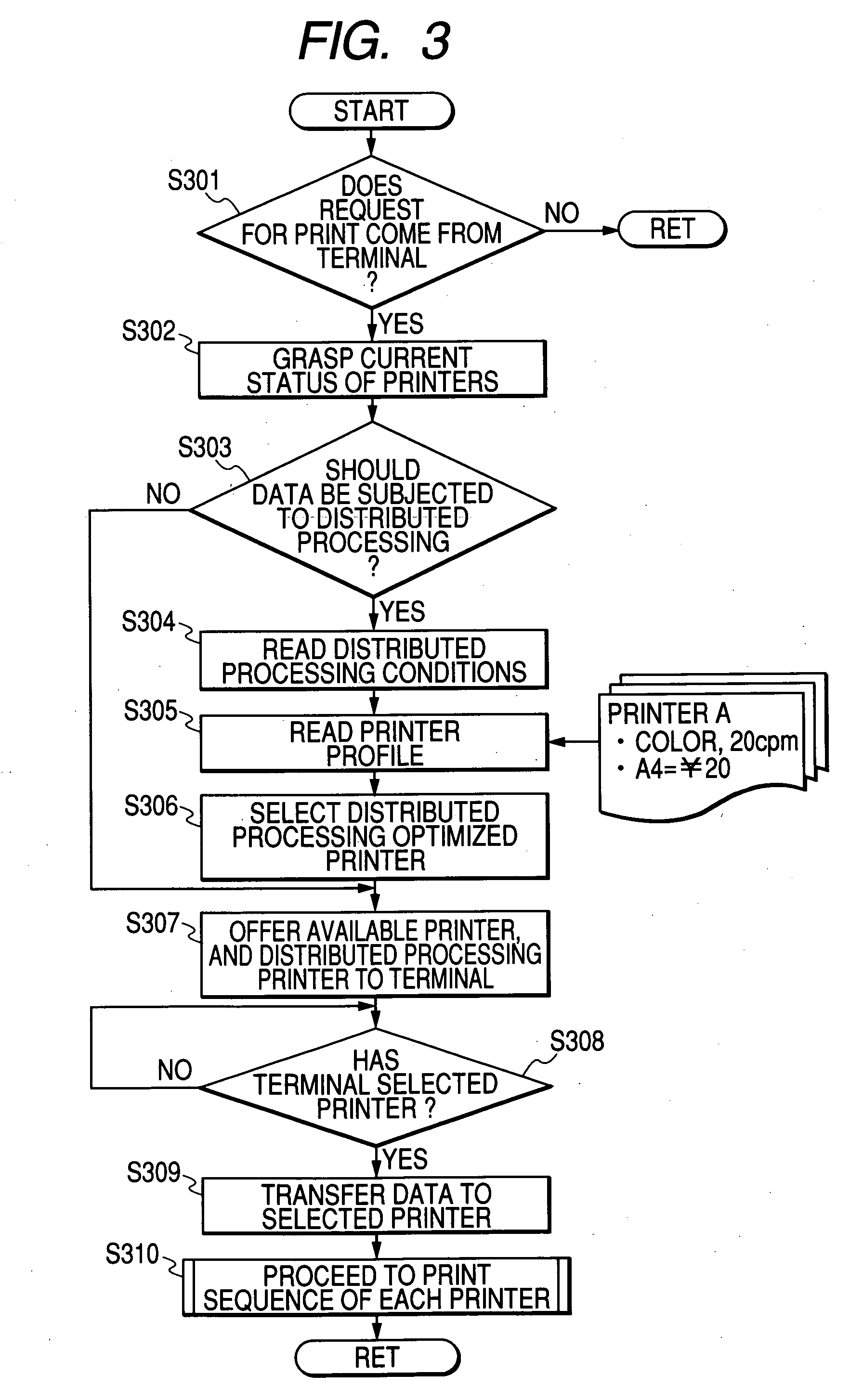
[0048] It is understood that a network environment is the same as that shown in FIG. 2, but in the present embodiment, at least printers (A and B) 11 and 12 are products by a manufacturer, and the control of FIG. 4 is effected by a printer server 14 to thereby enable the predominance, particularly economy, of the manufacturer's own image forming apparatuses to be appealed. Branch-off points given identical alphabetical letters in FIG. 4 shown that processing is continuous at those positions (this also holds true in the following drawings). The processing of FIG. 4 can also be executed by a terminal 10 and the printer server 14, but in the following description, it is to be understood that it is executed by the printer server 14.

[0049] The steps S401 to S405 of FIG. 4 are processes corresponding to the steps S301 to S305 of FIG. 3, and when as shown, distributed processing is selected, the processing until a printer profile is read is similar to that shown in FIG. 3.

[0050] In FIG. ...

second embodiment

[0065] In a second embodiment, there is shown an embodiment in an environment when as shown in FIG. 6, on the LAN 1, there exists an accounting server 15 for totalizing the printing situations of the respective printers through a status. In the other points, the construction of FIG. 6 is similar to that of FIG. 2.

[0066]FIG. 7 shows the control of the present embodiment. FIG. 7 is a flow chart of a form equal to that of FIG. 4, and use is made of step numbers of the order of 700, and the places 1 and 10 in the step numbers of the respective steps are made coincident with those of the corresponding steps of FIG. 4.

[0067] As shown, the entire processing of FIG. 7 is similar to that of FIG. 4, but at least the change data of the accounting condition at a step S717 is transmitted to the accounting server 15. Also, a printer profile read at step S705 and an accounting condition read at a step S717 may be individually obtained from each printer by the terminal 10 as in the first embodimen...

third embodiment

[0074] In a third embodiment, there is shown an embodiment in a case where in the LAN environment, there exists a printer having connected thereto an aftertreatment apparatus for effecting particular aftertreatment such as binding or sorting on printed sheets.

[0075] In FIG. 9, three printers (A to C) 21 to 23 are connected together on the LAN 1. The printers (A to C) 21 to 23 are equal to the printers (A to C) 11 to 13 of FIG. 2 or FIG. 6, but on the printer (A) 21 and the printer (C) 23, there are installed aftertreatment apparatuses 21a and 23a for effecting particular aftertreatment such as binding or sorting on printed sheets, and the particular aftertreatment is possible in synchronism with the outputting of these printers. Also, it is to be understood that (at least) the printer (A) 21 and the printer (C) 23 are provided with an inserter (or an onto sheet feeder or the like), and the particular aftertreatment (such as, for example, binding) can be effected on both of sheets ne...


PUM


Abstract

An image processing system for enabling a manufacturer's image forming apparatuses to be used as far as possible by a user. Design is made to enable a manufacturer or a vendor to appeal the predominance, particularly economy, of their own image forming apparatuses by the utilization of a user interface for controlling a recording process.

Description

BACKGROUND OF THE INVENTION [0001] 1. Field of the Invention [0002] The invention relates to an image processing system including a plurality of network-connected image forming apparatuses and record-processing record data by the use of at least two of the plurality of image forming apparatuses, a control method therefor and a control program therefor. [0003] 2. Description of the Related Art [0004] In image forming apparatuses such as copying machines and printers, there has heretofore been a contract form in which accounting is done for each print. In an accounting system for conventional image forming apparatuses, as shown in FIG. 1 of the accompanying drawings, it is often the case that for each kind of machine, a unit cost per print is predetermined. [0005] As a matter of course, a difference comes out in this unit cost of print depending on the types of apparatuses, the sizes of printing paper and the manner of printing (such as two sides). The example shown in FIG. 1 is an ex...

Claims


Application Information

Patent Timeline
IPC IPC(8): G03G15/00G03G21/02B41J29/38G06F3/12G06F15/00G06Q30/04G06Q30/06G06Q50/00H04N1/00
CPCG03G21/02G06Q30/0211G03G15/5087G06Q30/0226G06Q30/0224
Inventor ISEKI, YUKIMASAISOBE, YOSHINORIDOI, KOJIHIROMATSU, KENJIOYUMI, MASASHI
Owner CANON KK
Learn More