
Apparatus and a method for distributing a transmission power in a cellular communications network

a technology of cellular communications network and transmission power, applied in the direction of transmission monitoring, power management, wireless commuication services, etc., can solve the problems of significant addition of power strain on the ue, limited amount of power resources available, and even more challenges, so as to improve the mechanism of controlling uplink transmission power

Active Publication Date: 2005-09-22
SAMSUNG ELECTRONICS CO LTD
View PDF6 Cites 103 Cited by
  • Summary
  • Abstract
  • Description
  • Claims
  • Application Information

AI Technical Summary

Benefits of technology

[0014] It is an object of the present invention to improve the mechanisms to control uplink transmission power of a UE in a cellular communications network.
[0016] In this way the uplink transmission power of a UE can be controlled such that a loss of performance, particularly for some channels, is less likely or avoided.
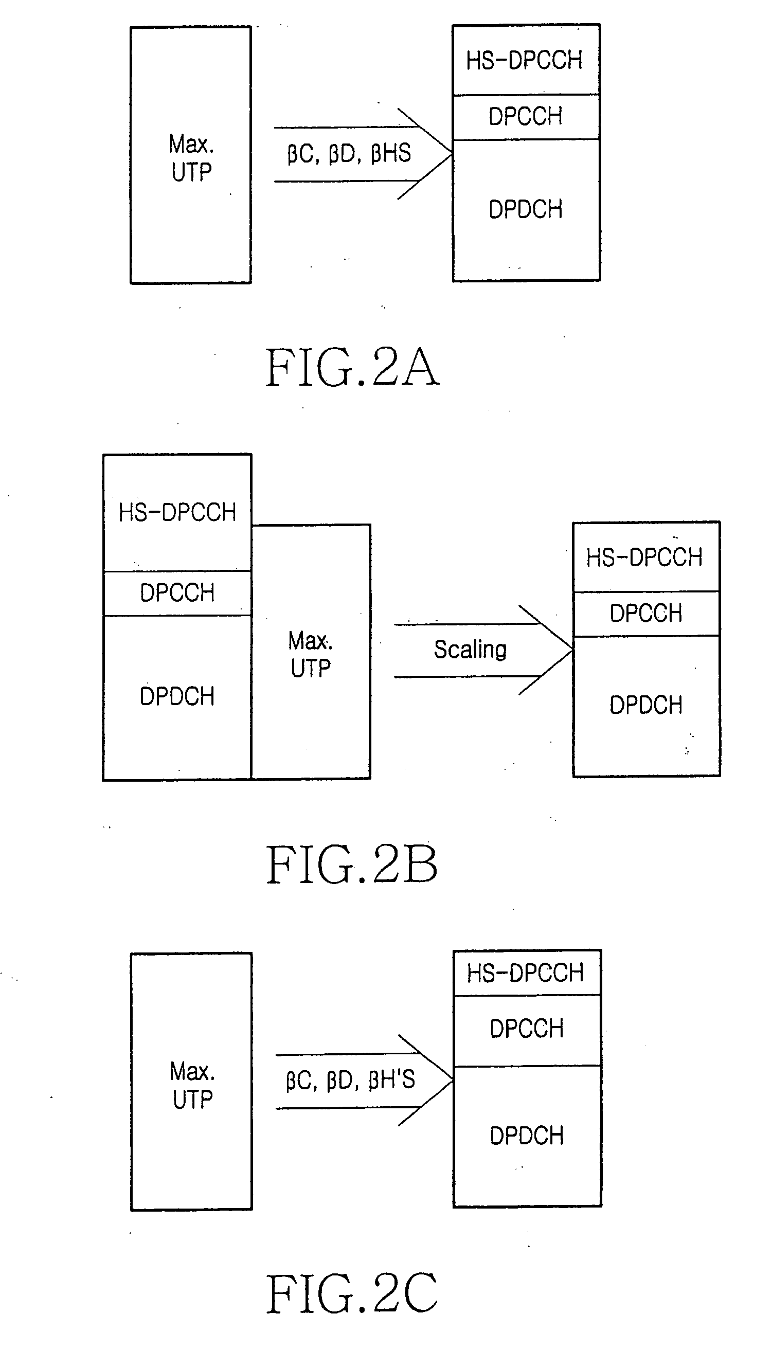
[0018] In this way, important or “high priority” channels are less affected by an uplink transmission power problem of a UE. For example, on important channels, such as the Dedicated Physical Data Channel (DPDCH) or the Dedicated Physical Control Channel (DPCCH), no or only reduced loss of performance is expected for higher layer 3 Radio Resource Control (RRC) signalling or high priority application such as a voice call.

Problems solved by technology

A user equipment (UE) for the use in cellular communications networks such as the Universal Mobile Telecommunications System (UMTS) has a limited amount of power resources available for transmitting user and control data in the uplink direction to the base stations of the network.
The introduction of multiple parallel services such as those available in UMTS has made things even more challenging.
The impact of this could be a significant addition of power strain on the UE.
This means that HSDPA capable UE's will have higher probability of experiencing a power problem.

Method used


Image

  • Apparatus and a method for distributing a transmission power in a cellular communications network
  • Apparatus and a method for distributing a transmission power in a cellular communications network
  • Apparatus and a method for distributing a transmission power in a cellular communications network

Examples


Embodiment Construction

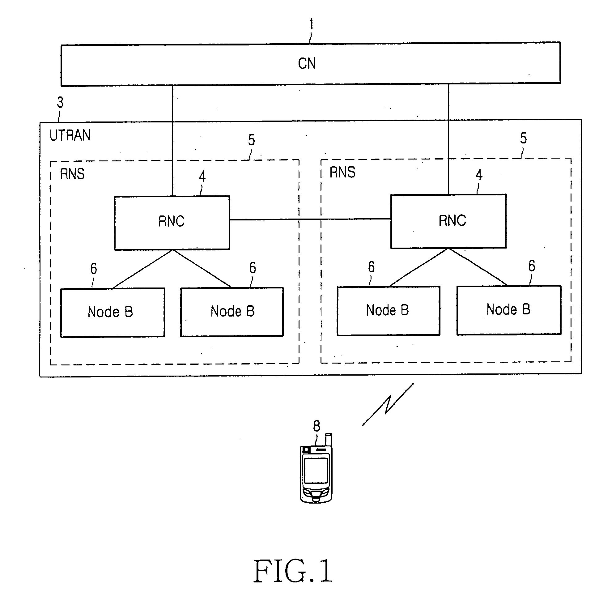
[0029] In FIG. 1 a schematic outline of a mobile telecommunications network according to the Universal Mobile Telecommunications System (UMTS) standard is shown. The typical architecture of such a network comprises mobile user equipments (UEs) 8, a UMTS Terrestrial Radio Access Network (UTRAN) 3 and one or more core networks (CNs) 1. UMTS is a third generation radio network using wideband code division multiple access (W-CDMA) technology.

[0030] The core network 1 may comprise Mobile Switching Centre (MSC) or Serving GPRS (General Packet Radio Services) Support Nodes (SGSN). The core network is connected via communication links to a number of Radio Network Controllers (RNCs) 4. The RNCs are dispersed geographically across areas served by the core network 1. Each RNC 4 controls one Radio Network Subsystems (RNSs) 5, including one or more base stations 6 such as “Nodes B” located remote from, and connected by further communication links to, the RNC 4. Each base station 6 transmits rad...


PUM


Abstract

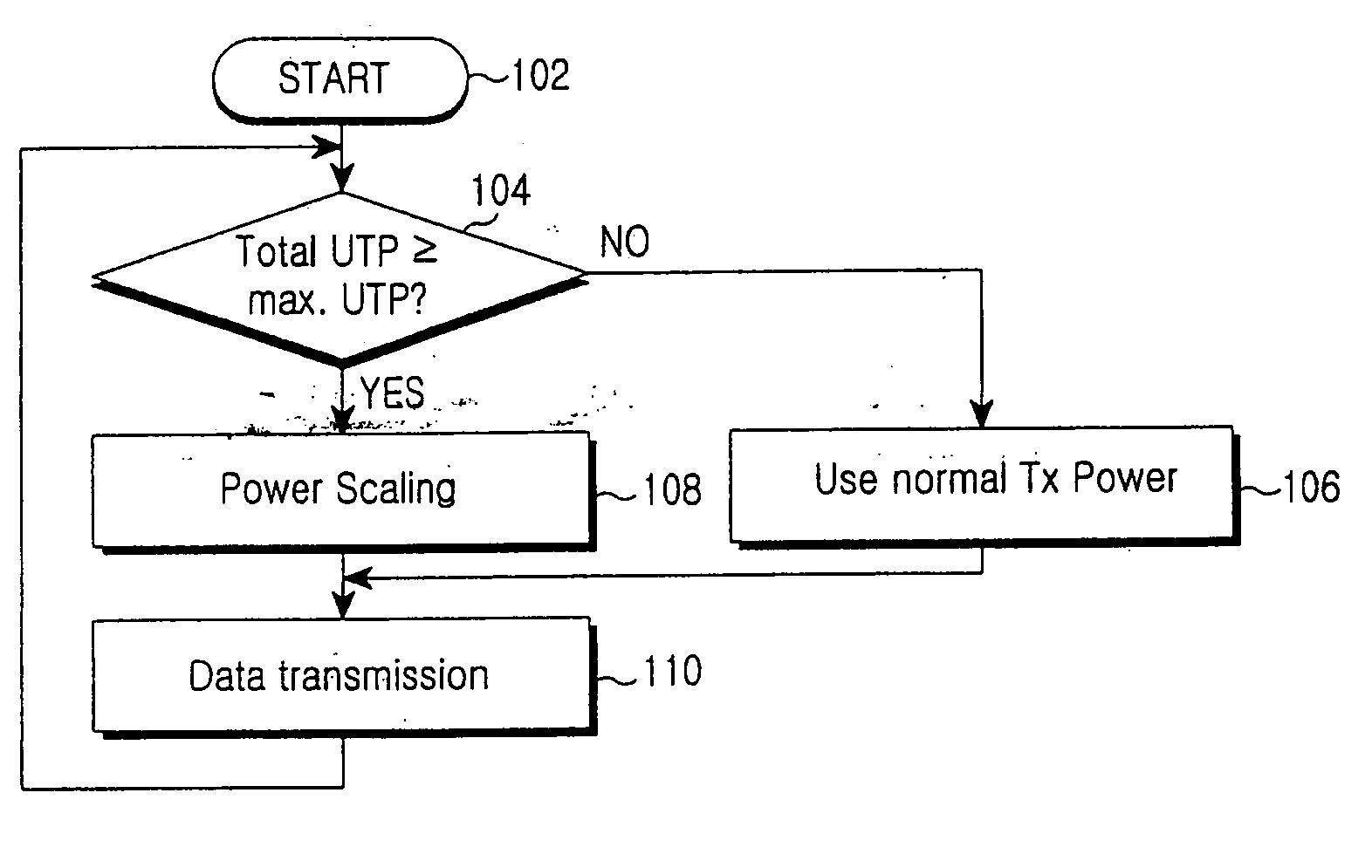
A mobile terminal for use in a cellular communications network the terminal being adapted to: i) if the terminal transmits signals at a power below the maximum uplink transmission power, distributing the available uplink transmission power between different channels according to a first scheme; and ii) if the terminal transmits signals at a power exceeding or about to exceed the maximum uplink transmission power, distributing the available uplink transmission power between different channels according to a second scheme different from said first scheme.

Description

PRIORITY [0001] This application claims priority to an application entitled “An Apparatus And A Method For Distributing A Transmission Power In A Cellular Communications Network”, filed in the United Kingdom Patent Office on Feb. 10, 2004 and assigned Serial No. 0402896.5, the contents of which are incorporated herein by reference. BACKGROUND OF THE INVENTION [0002] 1. Field of the Invention [0003] This invention relates to the field of power control in mobile communications networks. More particularly, but not exclusively, the invention relates to control of the uplink transmission power. [0004] 2. Description of the Related Art [0005] A user equipment (UE) for the use in cellular communications networks such as the Universal Mobile Telecommunications System (UMTS) has a limited amount of power resources available for transmitting user and control data in the uplink direction to the base stations of the network. Also, the network may limit the UE power allowed to transmit in the up...

Claims


Application Information

Patent Timeline
IPC IPC(8): H04B7/005H04J13/00H04W52/14H04W52/16H04W52/28H04W52/34H04W52/36
CPCH04W52/146H04W52/16H04W52/36H04W52/286H04W52/346H04W52/281H04B7/005H04W72/0473
Inventor HASSAN, RIZWAN
Owner SAMSUNG ELECTRONICS CO LTD
Learn More