Hydraulic turbine

a technology of hydropower turbines and turbines, applied in the direction of impulsive engines, machines/engines, sea energy generation, etc., can solve the problems of increased losses, increased surge load, and increased surge load, and achieve the effects of improving specific speed, efficiency, and design freedom

Inactive Publication Date: 2017-07-20
NATEL ENERGY
View PDF9 Cites 9 Cited by
  • Summary
  • Abstract
  • Description
  • Claims
  • Application Information

AI Technical Summary

Benefits of technology

[0009]The present invention relates to conversion of kinetic energy of a flowing fluid into shaft work, and in particular, to an improved system, method, and apparatus for a linear hydraulic cross-flow turbine. This new turbine retains some of the best characteristics of conventional free jet cross-flow turbines, including high efficiency over a wide range of flow rates and self-cleaning operation, while providing significant improvements in specific speed, efficiency, and design freedom enabling lower-cost civil works, especially at low head hydropower projects.
[0010]In one aspect of the invention, a turbine having two working stages in which the turbine blades move in substantially linear paths around a central array of stationary guidevanes, is provided with blades which have negative stagger angle in the first path, and positive stagger in the second path. This type of turbine results in efficient operation with the benefit of hydraulic forces that inherently support the blades in their path, avoiding risk of collision between the blades and stationary guidevanes without the need for complex support mechanisms.
[0012]The disclosed design has numerous comparative benefits in comparison to conventional high-flow hydraulic turbines including circular cross-flow turbines and Kaplan turbines. In comparison to the common circular cross-flow, the disclosed design effectively maximizes the “working zone” in the turbine. Instead of a narrow portion of the circumference of the circular runner which is used for crossing flow, the linear cross-flow has a long zone of cross-flow. Also this crossing flow can be well-conditioned with little turbulence, while in a circular cross-flow turbine the theoretical flow path actually crosses through itself, and also may collide with the necessary drive shaft, creating additional losses. Furthermore, a significant fraction of the flow in a circular cross-flow turbine becomes “entrained” in the vanes circumferentially, contributing to a loss in performance. The portion of entrained flow in the linear cross-flow is minimized in comparison to the working (linear) portion. As a consequence the maximum efficiency of the present design can be higher than real-world circular cross-flow turbines. There are a number of other important advantages, such as the fact that the disclosed invention can be built with a true free-jet nozzle, which allows the use of a jet deflector plate similar in concept to the design commonly deployed in Pelton turbines. This jet deflector can allow instantaneous de-powering of the turbine in the event of grid fault, preventing runaway while preventing any water hammer or surge. These types of surge loads often are so large that they drive the design of the penstock and other pipeline equipment. By being able to be configured with a deflector, the linear cross-flow can significantly reduce the total cost of hydropower plants.

Problems solved by technology

Also this crossing flow can be well-conditioned with little turbulence, while in a circular cross-flow turbine the theoretical flow path actually crosses through itself, and also may collide with the necessary drive shaft, creating additional losses.
Furthermore, a significant fraction of the flow in a circular cross-flow turbine becomes “entrained” in the vanes circumferentially, contributing to a loss in performance.
These types of surge loads often are so large that they drive the design of the penstock and other pipeline equipment.

Method used


Image

  • Hydraulic turbine
  • Hydraulic turbine
  • Hydraulic turbine

Examples


Embodiment Construction

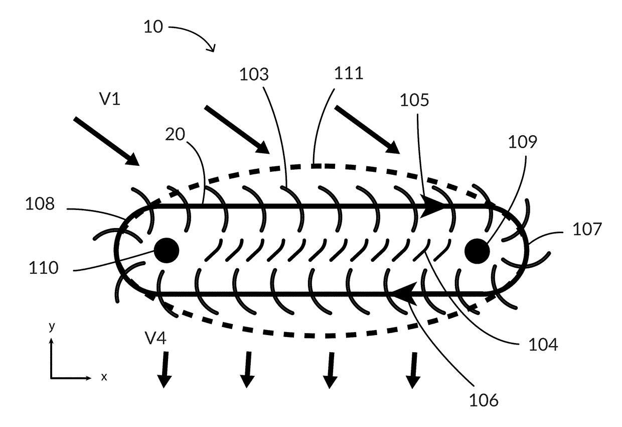
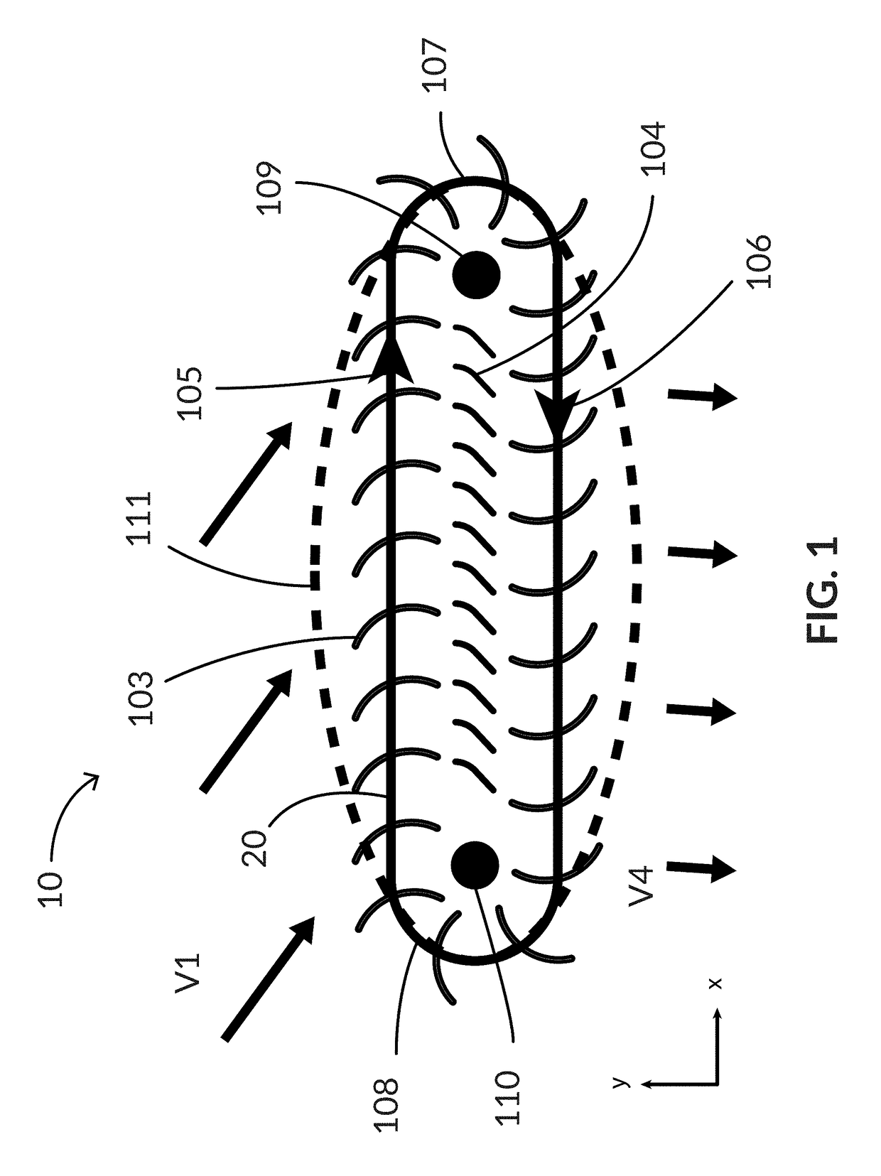
[0138]As shown in FIG. 1, a turbine 10 can include a first axis 109 and a second axis 110. First axis 109 and second axis 110 can be parallel. First axis 109 and second axis 110 can be spaced along a horizontal direction. In another aspect, first axis 109 and second axis 110 can be spaced along a vertical direction. In another aspect, first axis 109 and second axis 110 can be spaced along a plane at some angle relative to horizontal, between horizontal and vertical.

[0139]The turbine 10 can include blades 103 that can move in a path consisting of multiple segments between and around first axis 109 and second axis 110. For example, blades 103 can move through a first segment 105 from second axis 110 toward first axis 109, a second segment 107 around first axis 109, a third segment 106 from first axis 109 toward second axis 110, and a fourth segment 108 around second axis 110. After fourth segment 108, blades 103 can re-enter first segment 105. First segment 105 and third segment 106 c...


PUM


Abstract

Disclosed herein are linear hydraulic turbines in which the linear machine converts the majority of available energy in the flowing water into useful torque directly in the runner, leaving the outflow with very little velocity.

Description

CROSS-REFERENCE TO RELATED APPLICATION[0001]This application is a continuation of U.S. application Ser. No. 15 / 149,984 filed May 9, 2016 which claims the benefit of U.S. Provisional Patent Application No. 62 / 158,170, filed May 7, 2015, which is incorporated herein by reference in its entirety.BACKGROUND[0002]Cross-flow turbines with circular cross-section are commonly known and have been widely used in hydropower applications around the world for many decades.[0003]This type of turbine operates on a free-jet principle, utilizing a nozzle to direct high velocity fluid flow through a runner. This runner can consist of multiple blades of circular arc section arrayed about a single axis, comprising in their entirety a cylindrical shape. Water flows through the cylinder in a direction perpendicular to the cylinder axis, so that the fluid performs work on two different areas of the circumferential blades. By design, this type of turbine extracts most of the kinetic energy in the flowing w...

Claims


Application Information

Patent Timeline
Patent Type & Authority Applications(United States)
IPC IPC(8): F03B1/04F03B11/00F03B1/02
CPCF03B1/04F03B1/02F05B2240/123F05B2220/32F03B11/004F05B2240/12F05B2240/1231F05B2240/13F05B2240/244F03B7/006F03B11/02Y02E10/20Y02E10/30
Inventor SCHNEIDER, ABRAHAM D.
Owner NATEL ENERGY
Why Eureka
Try Eureka