Seal guard for compactor

a compactor and seal guard technology, applied in the direction of wheel attachments, vehicle maintenance, vehicle cleaning, etc., to achieve the effect of reducing performan

Active Publication Date: 2010-06-08
FREEMAN ERNIE
View PDF12 Cites 9 Cited by
  • Summary
  • Abstract
  • Description
  • Claims
  • Application Information

AI Technical Summary

Benefits of technology

[0003]The invention is directed to a novel guard for use at each wheel of a compactor used in a landfill or similar operation. The guard design is inspired, in part, by the realization that a primary source of axle seal failure in such environments is the forced entry of a strand of wire, cable or like high-tensile strength material into the plane of contact of the sealing elements. The guard of the present invention is arranged, as a first measure of wheel seal protection, with mechanical narrow gap seal elements intended to exclude debris, especially stranded material, from entering the zone of the respective wheel seal. As a second measure of defense, the guard is provided with an essentially closed annular space surrounding the seal that is intended to trap any debris that might get past the first mechanical seal. The trap can be especially effective when stranded debris enters the annular zone. This type of debris, to the extent that it is being forcibly wrapped around the axle by motion of the wheel is harmlessly wrapped onto and thereby trapped by a spool-like hub flanged at both its ends. Debris getting past the narrow gap seal is thereby trapped by this wrapping action.
[0004]In the disclosed embodiment, the guard is formed as semi-circular segments to enable its installation on an axle without disassembly of the final drive. Additionally, in the preferred embodiment, the guard is provided with two supplemental interior mechanical seals. The seals are in series with each other and with the primary exterior narrow gap seal with reference to the path that any debris must follow to reach the wheel seal. The structures that form the end boundary of the annular debris trapping zone serve to form the interior mechanical guard seals. Additionally, an outboard, cantilever supported, one of the end boundary structures seals with the axle assembly itself. This structure, ideally, is a sufficiently close clearance fit with the axle so that this cantilevered end can be directly supported by the axle when foreign objects are jammed against its exposed surfaces thereby resisting permanent distortion and consequent loss of performance.

Problems solved by technology

This type of debris, to the extent that it is being forcibly wrapped around the axle by motion of the wheel is harmlessly wrapped onto and thereby trapped by a spool-like hub flanged at both its ends.

Method used


Image

  • Seal guard for compactor
  • Seal guard for compactor
  • Seal guard for compactor

Examples


Embodiment Construction

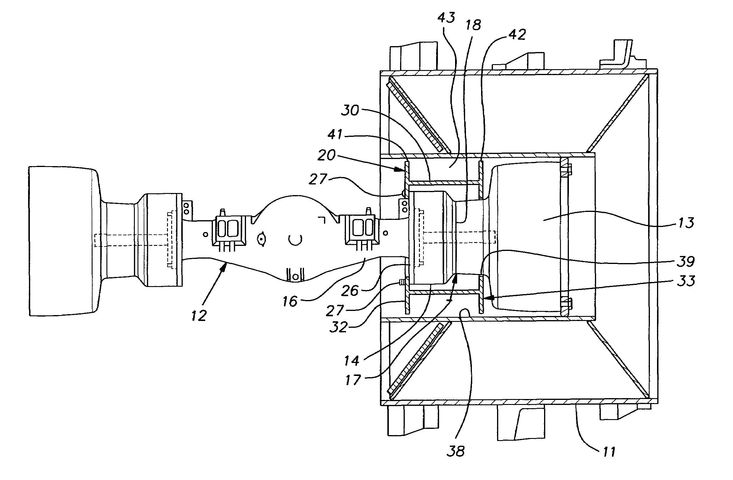
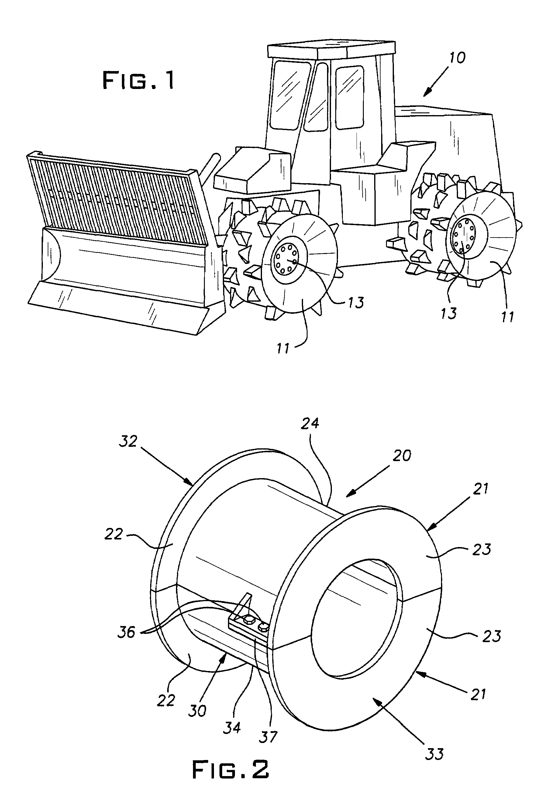
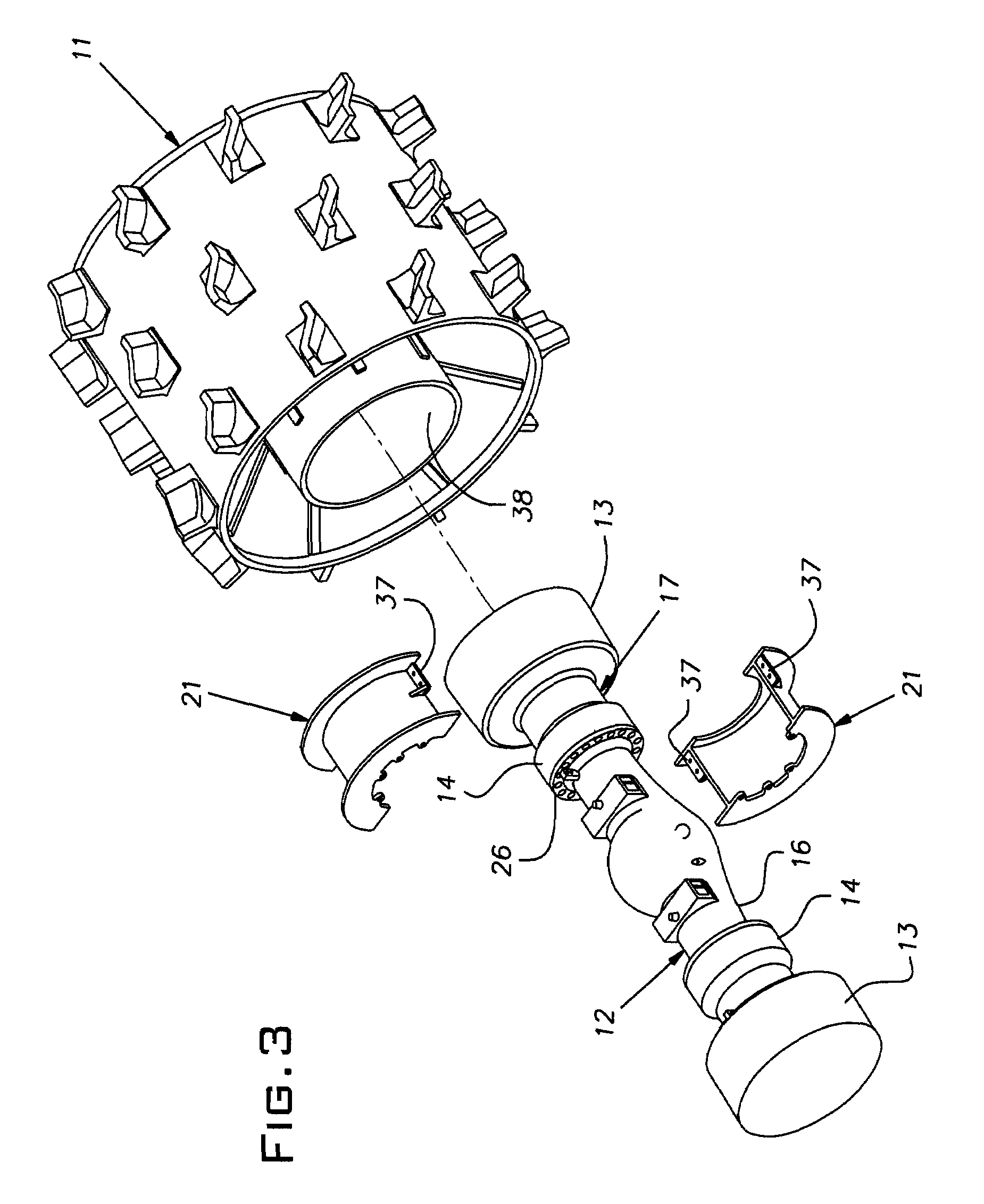
[0009]The invention has utility with wheeled tractors, known in the industry as compactors. Compactors are relatively heavy machines, fitted with steel wheels, that are driven back and forth over refuse dumped in a landfill. Compaction of the debris allows more refuse to be received in a given volume of landfill space. A conventional wheeled tractor or compactor 10 is schematically shown in FIG. 1. The compactor 10, as is common, has a pair of axles with each axle carrying a wheel 11 on each side of the machine so that the compactor has four wheels. On large equipment such as manufactured by Caterpillar® under Model Nos. D6 through D12, each side of an axle 12 has a final drive 13 on its outboard end to which a respective wheel 11 is bolted. Rotation of a wheel 11 requires relative rotation between the final drive 13 and a spindle 14 bolted in fixed relation to a housing 16 of the axle. In the case of a Caterpillar compactor, this relative rotation is accommodated by a so-called duo...


PUM


Abstract

A guard for the axle seal of a wheeled tractor being an annular steel structure that bridges the plane of the seal between a spindle and final drive including a pair of axially spaced flanges having circular outer peripheries, at least one of the outer peripheries of the flanges being sized to produce a narrow gap seal with a circular interior surface of a wheel rim, a hub extending axially between the flanges and spaced radially inward of said flange outer peripheries, the flanges, hub and interior wheel surface defining an annular space adapted to trap debris.

Description

BACKGROUND OF THE INVENTION[0001]The invention relates to improvements in protective devices for drive lines of heavy equipment operating in adverse environments such as landfills.PRIOR ART[0002]Compactors in the form of heavy wheeled tractors are used in the landfill industry to compact refuse for full utilization of the landfill space. U.S. Pat. Nos. 5,330,260, 5,451,100, 5,553,932, and 5,820,230 disclose a type of cutting device associated with the wheels of a compactor. The cutter devices operate to sever strands of material that would otherwise wrap around the axle, accumulate and develop excessive friction and / or find their way into a seal area between the rotating and non-rotating parts and destroy the seal. Seal destruction results in expensive drive line repairs and loss of machine time when the compactor is being repaired. The patented cutters have proven to be effective for some machines, but have not been widely adopted on certain large machines that have proven to suffe...

Claims


Application Information

Patent Timeline
Patent Type & Authority Patents(United States)
IPC IPC(8): B62D25/16A01B17/00
CPCB60B3/085B60B7/00B60B7/06B60B37/04B60B7/14B60B15/025B60B35/121B60B7/061
Inventor FREEMAN, ERNIE
Owner FREEMAN ERNIE
Why Eureka
Try Eureka