Impingement cooling of turbine blades or vanes

a technology of impingement cooling and turbine blades, which is applied in the direction of liquid fuel engines, vessel construction, marine propulsion, etc., can solve the problems of inefficient impingement cooling in the downstream regions of the impingement cooling zone, dislocation and possible failure of the blade or the wing, etc., and achieves convenient construction, good cooling properties, and satisfactory alignment of the impingement device.

Inactive Publication Date: 2015-01-15
SIEMENS AG
View PDF7 Cites 10 Cited by
  • Summary
  • Abstract
  • Description
  • Claims
  • Application Information

AI Technical Summary

Benefits of technology

[0087]To provide the turbine assembly with good cooling properties and a satisfactory alignment of the impingement device in the aerofoil, the hollow aerofoil comprises at least a spacer at the inner surface of the cavity of the hollow aerofoil to

Problems solved by technology

The effect of temperature on the turbine blades and/or stator vanes can be detrimental to the efficient operation of the turbine and can, in extreme circumstances, lead to distortion and possible failur

Method used


Image

  • Impingement cooling of turbine blades or vanes
  • Impingement cooling of turbine blades or vanes
  • Impingement cooling of turbine blades or vanes

Examples


Embodiment Construction

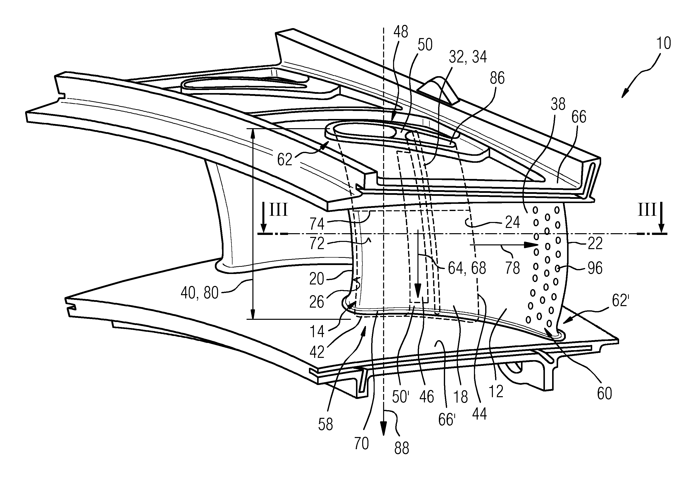
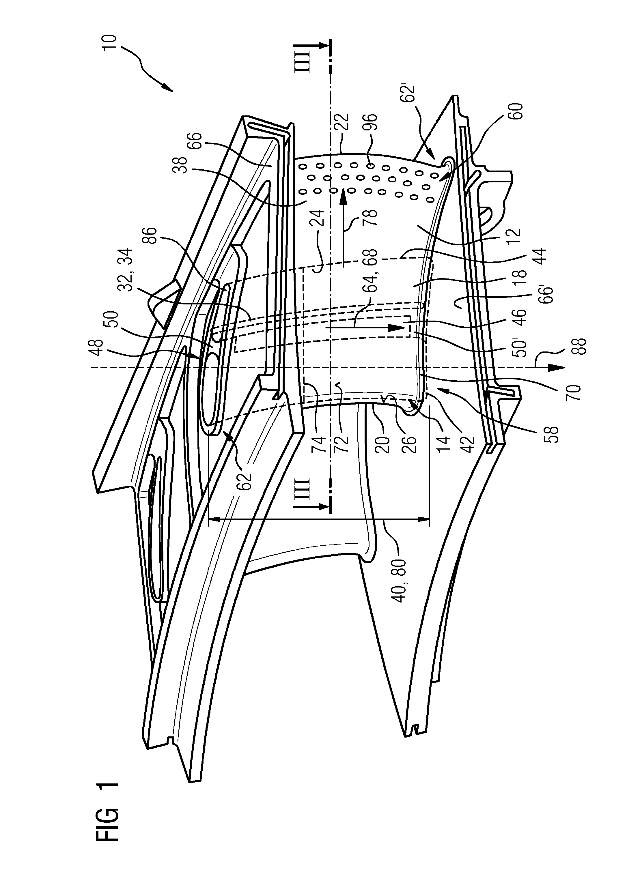
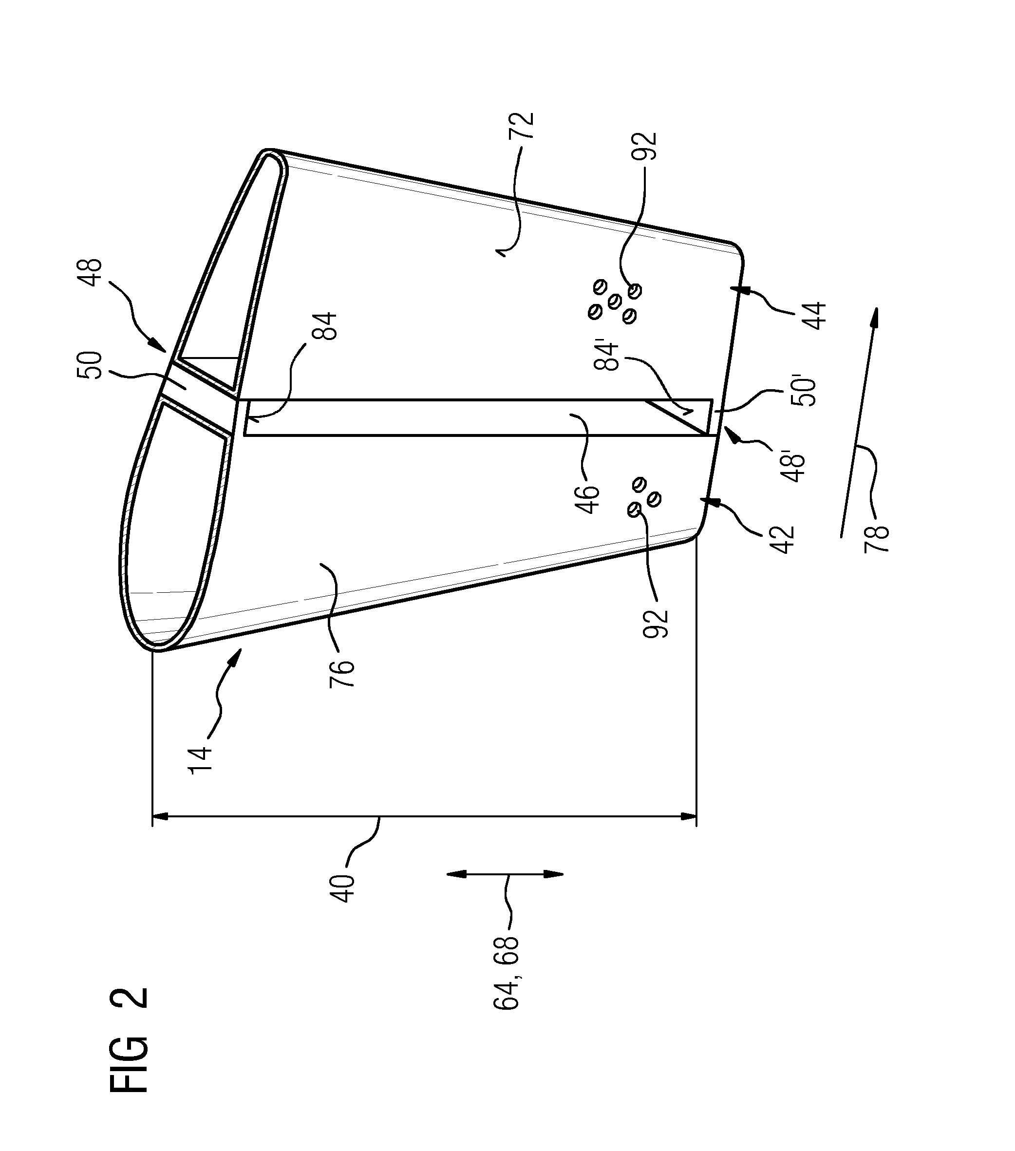
[0104]In the present description, reference will only be made to a vane, for the sake of simplicity, but it is to be understood that the invention is applicable to both blades and vanes of a turbine.

[0105]FIG. 1 shows in a perspective view a turbine assembly 10, in this case a double vane segment. The turbine assembly 10 comprises a basically hollow aerofoil 12, which is referred to as aerofoil 12 in the following text and is embodied as a vane, with two cooling regions, specifically, an impingement cooling region 58 and a trailing edge cooling system 60 (i.e. a pin-fin / pedestal cooling region). The former is located towards a leading edge 20 and the latter towards a trailing edge 22 of the aerofoil 12. At two radial ends 62, 62′ of the aerofoil 12, which are arranged in a radial direction 64 opposed towards each other at the aerofoil 12, two platforms, referred to in the following text as an outer platform 66 and an inner platform 66′, are arranged. The outer platform 66 and the in...


PUM


Abstract

A turbine assembly having a hollow aerofoil and impingement device, the aerofoil having a first side wall from leading to trailing edge and a cavity arranged a distance to an inner surface of the cavity for impingement cooling and a flow channel for cooling medium from the leading to trailing edge, the impingement device has first and second pieces arranged side by side, the second piece downstream of the first forming a first flow passage providing passage from one side of the aerofoil towards an opposite side. A blocking element is arranged in the flow channel between the second piece and first side wall at a suction side for blocking flow of cooling medium from leading to trailing edge denying access to a section of the flow channel downstream of the blocking element while directing cooling medium in the first flow passage away from the suction side towards pressure side.

Description

CROSS REFERENCE TO RELATED APPLICATIONS[0001]This application is the US National Stage of International Application No. PCT / EP2012 / 073353 filed 22 Nov. 2012, and claims the benefit thereof. The International Application claims the benefit of European Application No. EP12155540 filed 15 Feb. 2012. All of the applications are incorporated by reference herein in their entirety.FIELD OF THE INVENTION[0002]The present invention relates to an aerofoil-shaped turbine assembly such as turbine rotor blades and stator vanes, and to impingement tubes used in such components for cooling purposes.BACKGROUND TO THE INVENTION[0003]Modern turbines often operate at extremely high temperatures. The effect of temperature on the turbine blades and / or stator vanes can be detrimental to the efficient operation of the turbine and can, in extreme circumstances, lead to distortion and possible failure of the blade or vane. In order to overcome this risk, high temperature turbines may include hollow blades o...

Claims


Application Information

Patent Timeline
IPC IPC(8): F01D5/18F01D9/02
CPCF05D2260/201F01D5/187F01D9/02F01D5/189F01D5/20F01D5/18
Inventor MUGGLESTONE, JONATHAN
Owner SIEMENS AG
Why Eureka
Try Eureka