Plug-type connection for releasably connecting two bodies

US20050209592A1Inactive Publication Date: 2005-09-22DEPUY SYNTHES PROD INC

Image

  • Plug-type connection for releasably connecting two bodies
  • Plug-type connection for releasably connecting two bodies
  • Plug-type connection for releasably connecting two bodies

Examples


Embodiment Construction

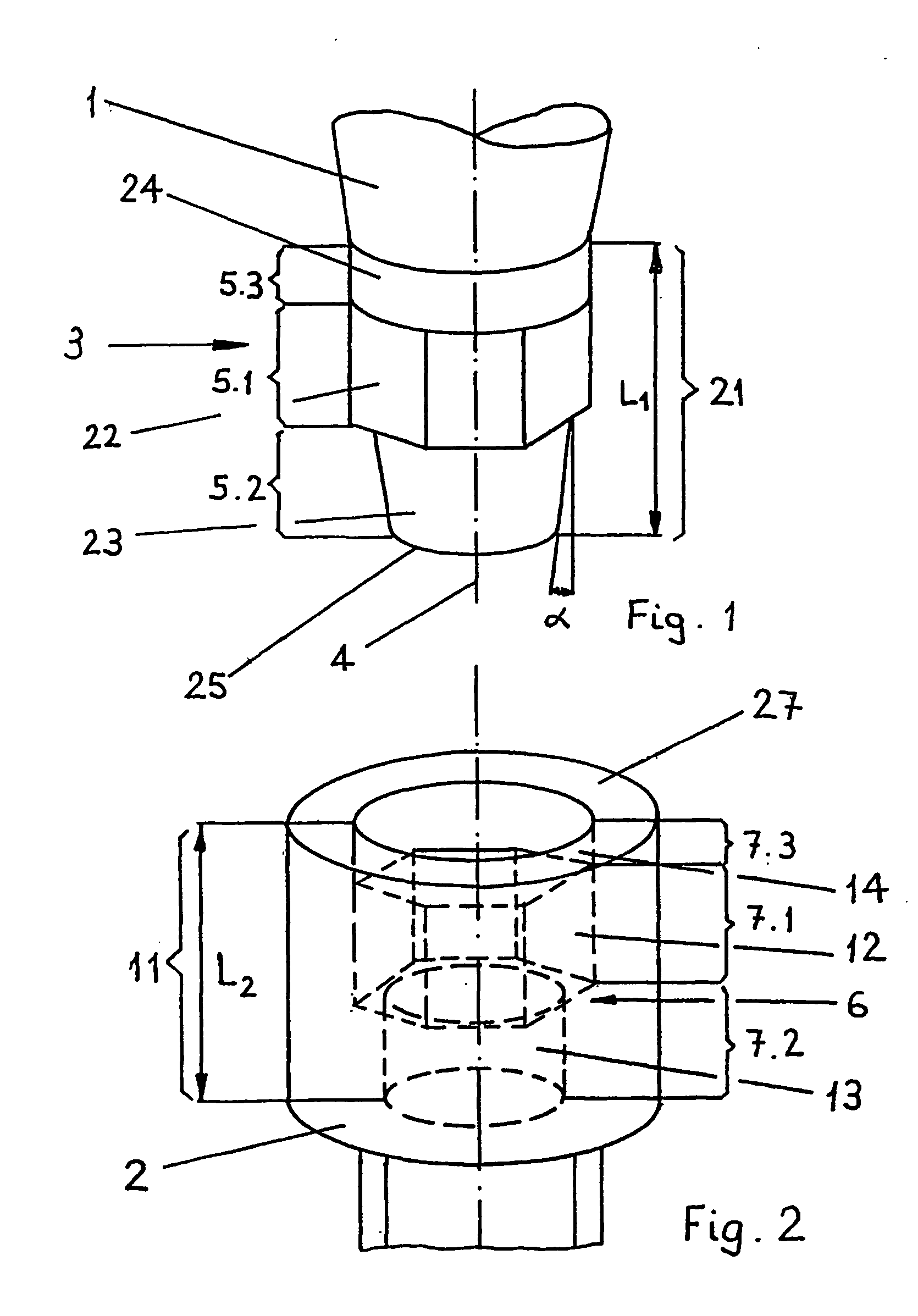
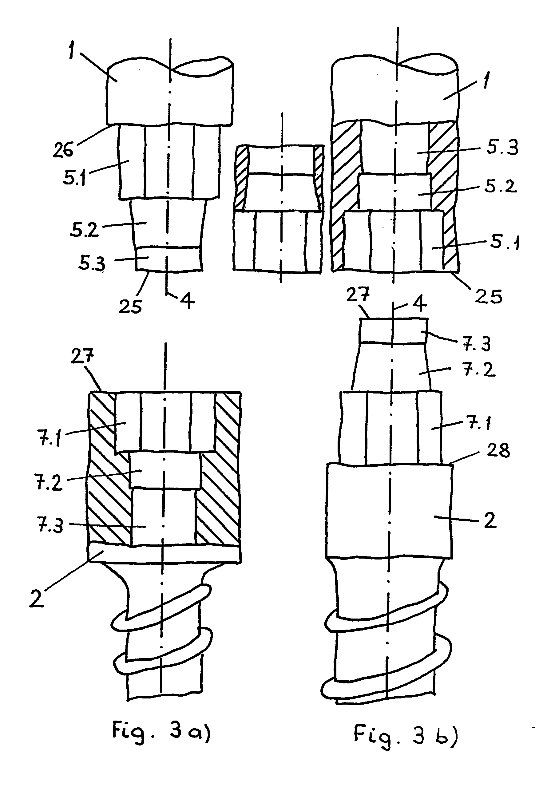
[0038]FIGS. 1 and 2 represent an embodiment of the plug-type connection according to the invention which comprises a first body 1 having a first connection zone 3 extending concentrically to a central axis 4 and a second body 2 having a connection zone 6 which equally extends concentrically to said central axis 4. Adjoining its front end 25, the body 1 comprises the first connection zone 3 including three (M=3) connection segments 5.1; 5.2; 5.3, which axially adjoin one another, beginning from the front end 25, and extend over a length L1. The connection zone 3 is shaped in the form of a shaft segment 21 extending concentrically to the central axis 4. The first connection segment 5.1 with a non-circular cross section Q5.1 is shaped in the form of a hexagonal segment 22 and has a width across corners E and a width across flats SW, whereas the first connection segment 5.2 designed for establishing an axially non-positive connection is shaped in the form of a frusto-conical shaft segme...


PUM


Abstract

The present invention relates to a plug-type connection for releasably connecting two bodies wherein the first body includes a first connection zone having a plurality of coaxially aligned first connection segments and the second body includes a plurality of coaxially aligned second connection segments. The first connection segment includes at least one segment with a non-circular cross-section and at least one segment having an axially tapering cross-section. The second connection segment includes at least one segment with a non-circular cross section sized and configured for rotatively engaging the non-circular cross section of the first connection segment and at least one segment sized and configured to mate with the at least one tapering section, wherein the tapered section of the first connection segment and the mating section of the second connection segment form an axially non-positive engagement for guiding the first body into engagement with the second body. The axially tapering cross-section of the first connection segment is preferably made from a deformable material so that the axially tapering cross section deforms when it mates with the second connection segment.

Description

CROSS-REFERENCE TO RELATED APPLICATIONS [0001] This application is a continuation-in-part of U.S. patent application Ser. No. 10 / 291,386 filed Nov. 12, 2002, which is a continuation of International Patent Application PCT / CH00 / 00263, filed May 11, 2000, the entire contents of which are expressly incorporated herein by reference thereto.FIELD OF THE INVENTION [0002] The invention relates to a plug-type connection for releasably connecting two bodies and in particular to a detachable connection between a pedicle screw and a screw driver. BACKGROUND OF THE INVENTION [0003] For a minimally invasive and endoscopic use of surgical instruments and implants it is extremely important to establish a firm connection between screw and screwdriver. With screws having large head dimensions firm connections are no problem. [0004] Small-headed screws having hexagon sockets present problems due to the small dimensions. It is, however, possible to use a screwdriver with a conical hexagon insert bit. ...

Claims


Application Information

Patent Timeline
22 Sep 2005
Publication
US20050209592A1
IPC
A61B17/58; A61B17/88; B25B15/00; B25B23/10; F16B23/00
CPC
A61B17/8875; F16B23/0007; B25B23/108; B25B15/008
Inventors
SCHLAPFER, FRIDOLIN; HESS, MARTIN