Storage system

a storage system and storage system technology, applied in the field of storage system technology, can solve the problems of overhead generation and the inability to maximize the performance of processors, and achieve the effect of improving the performance of data input/output processing of the storage system

Inactive Publication Date: 2005-09-22
GOOGLE LLC
View PDF7 Cites 17 Cited by
  • Summary
  • Abstract
  • Description
  • Claims
  • Application Information

AI Technical Summary

Benefits of technology

[0011] Thus, according to the present invention, a plurality of processors are provided in a disk controller that controls the input / output of data with respect to the disk devices, and a dedicated memory, superordinate interface and subordinate interface are provided for each processor. Thus, the plurality of processors execute the input / output processing requested from a superordinate device by executing the operating program by accessing respective memories dedicated for their exclusive use and controlling a superordinate interface and subordinate interface provided for their exclusive use. Thereby, improved performance of data input / output processing of a storage system can be achieved.

Problems solved by technology

However, when the technology of Laid-open Japanese Patent Application No. 2003-006174 is applied to a storage system, the following problems arise.
Therefore, in the system described in Laid-open Japanese Patent Application No. 2003-006174, there is the problem that contention occurs in accessing shared memory, when a plurality of processors execute processing, such as data input / output processing.
Therefore, in the system of Laid-open Japanese Patent Application No. 2003-006174, an overhead is generated by the processing used to synchronize the data stored in the caches.
Thus, in application of the technology of Laid-open Japanese Patent Application No. 2003-006174, as described above, to a storage system, there is the problem that the performance of the processors cannot be exploited to the maximum.

Method used


Image

  • Storage system
  • Storage system
  • Storage system

Examples


first embodiment

[0024] First of all, a first embodiment of the present invention will be described.

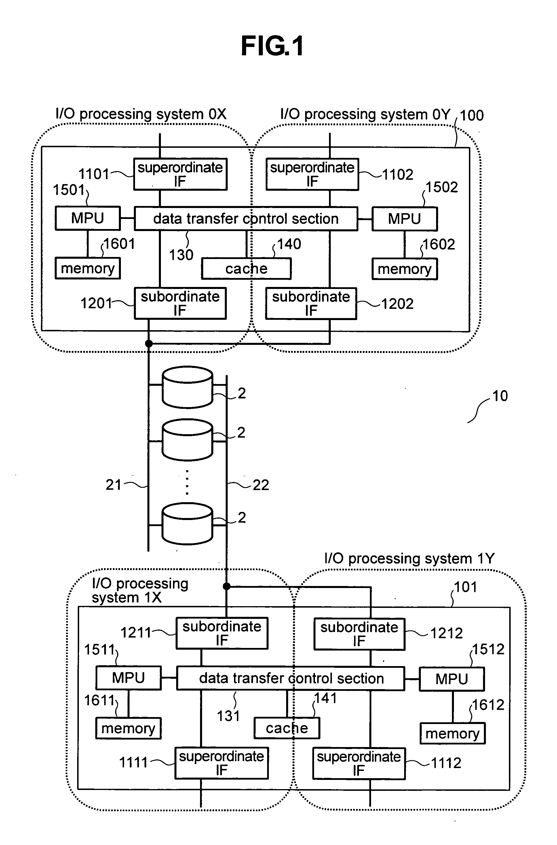
[0025]FIG. 1 is a diagram of a storage system according to a first embodiment of the present invention. As shown in the Figure, the storage system 10 comprises controllers 100 and 101 that control a storage system 10, at least one disk device 2 that stores data transmitted from a host computer (not shown) constituting a superordinate device, and loops (hereinbelow referred to as “back-end loops”) 21, 22 that perform transfer of data and that are connected with the controllers 100, 101 and the disk device 2. Although not shown in FIG. 1, the storage system 10 may be connected with a management terminal for input of various types of settings from the user (the management terminal will be described below).

[0026] The controller 100 performs input / output processing of data between a host computer and the disk device 2. Specifically, the controller 100 comprises superordinate IFs 1101, 1102, subordinate I...

second embodiment

[0087] A second embodiment of the present invention will be described. In this second embodiment, a construction for expanding the bandwidth of the back-end loop is added to the construction of the storage system 10 of the first embodiment. In the description of the second embodiment, items which are the same as those described in the case of the first embodiment are given the same reference symbols.

[0088] The storage system 10 according to the second embodiment is configured such that the bandwidth of the back end can be set in a back-end shared mode (hereinbelow referred to as the “standard mode”) and a back-end non-shared mode (hereinbelow referred to as an “expanded bandwidth mode”).

[0089] As shown in FIG. 1, the standard mode is a configuration in which disk devices 2 are connected to the back-end loops 21, 22. Specifically, as shown in FIG. 1, the subordinate IFs 1201, 1202 of the controller 100 are connected to a single back-end loop 21. The subordinate IFs 1211, 1212 of th...

third embodiment

[0124] Next, a third embodiment of the present invention will be described. In the third embodiment, the cache and data transfer control section that are provided by the controller 100 of the storage system 10 of the first embodiment are arranged to be independently provided for each IO processing system. In the description of the third embodiment, items that are the same as those described in the case of the first embodiment are given the same reference symbols.

[0125]FIG. 8 is a diagram of a storage system according to the third embodiment of the present invention.

[0126] As shown in FIG. 8, the storage system 11 comprises controllers 102 and 103 that control the storage system 10, at least one or more disk devices 2 that store data from a host computer, which is not shown, and loops (back-end loops) 21, 22 that perform transfer of data and connect the controllers 102, 103 and the disk devices 2.

[0127] It should be noted that the construction of the disk devices 2 and the back-en...


PUM


Abstract

It is an object to achieve higher performance of input/output processing in a storage system. In a disk controller of a storage system having disk devices and a disk controller that controls input/output of data to/from the disk devices and that accepts requests from a superordinate device, there are provided a memory, a superordinate IF and a subordinate IF (1201), for the exclusive use of each MPU.

Description

CROSS-REFERENCES TO RELATED APPLICATIONS [0001] This application relates to and claims priority from Japanese Patent Application No. 2004-082823, filed on Mar. 22, 2004, the entire disclosure of which is incorporated herein by reference. BACKGROUND OF THE INVENTION [0002] The present invention relates to storage system technology; and, in particular, the invention relates to a technique for achieving a high-performance storage system wherein a plurality of processors are incorporated in a controller. [0003] Conventionally, there is a multi-processor construction (for example, see Laid-open Japanese Patent Application No. 2003-006174) employing SMP (symmetric multi-processing) as a means of improving the performance of a computer system. In Laid-open Japanese Patent Application No. 2003-006174, parallel processing is made possible by arranging for a plurality of processors to share computer resources, such as memory. SUMMARY OF THE INVENTION [0004] Storage systems, typified by disk a...

Claims


Application Information

Patent Timeline
Patent Type & Authority Applications(United States)
IPC IPC(8): G06F3/06G06F12/00G06F12/08
CPCG06F3/0605G06F3/0613G06F2206/1008G06F3/0689G06F12/0866G06F3/0658
Inventor MIZUNO, YOICHIMATSUNAMI, NAOTONISHIMOTO, AKIRA
Owner GOOGLE LLC
Why Eureka
Try Eureka