Mountings for riving knives of table saws

a technology of table saws and mountings, which is applied in the field of cutting tools, can solve the problems of troublesome and time-consuming operations of known table saws, degraded overall operability of table saws, and troublesome and time-consuming mounting and removal operations of riving knives 304

Active Publication Date: 2005-09-29
MAKITA CORP
View PDF15 Cites 120 Cited by
  • Summary
  • Abstract
  • Description
  • Claims
  • Application Information

AI Technical Summary

Benefits of technology

[0067] In a further embodiment, the first knife portion is positioned further from the cutting blade than the second knife portion. The riving knife includes a cover vertically pivotally mounted to an upper portion of the first knife portion in order to cover and uncover the cutting blade. Therefore, in order to perform a groove forming operation, the fist knife portion may be removed together with the cover. The groove forming operation can then be readily performed with the aid of the second knife portion.

Problems solved by technology

As described above, the known table saws require troublesome and time-consuming operations for removing and remounting a riving knife in addition to a cover C and support block in order to a groove forming operation.
Therefore, the overall ease of operability of the table saws is degraded.
Therefore, the mounting and removing operations of the riving knife 304 can be troublesome and time consuming.
However, the divided riving knife causes an additional problem.
As a result of such a thin thickness, them is a difficulty in maintaining the positions of the first and second portions of the riving knife within a single plane.
In some cases, the separate components of the riving knife may not smoothly enter the split of the workpiece.
The operability of the table saw is subsequently degraded in this respect and a cutting operation cannot be efficiently performed.

Method used


Image

  • Mountings for riving knives of table saws
  • Mountings for riving knives of table saws
  • Mountings for riving knives of table saws

Examples


first representative embodiment

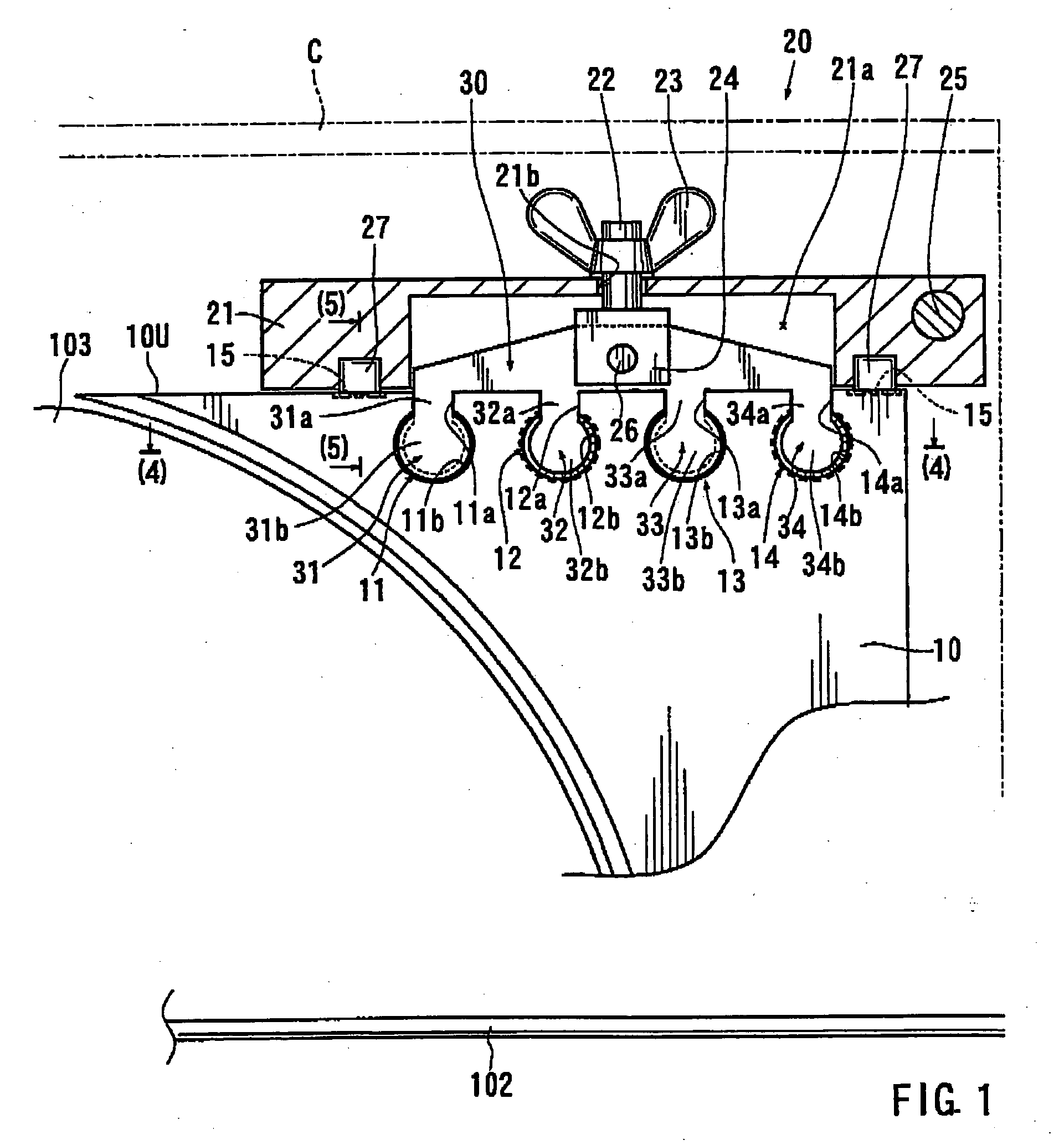
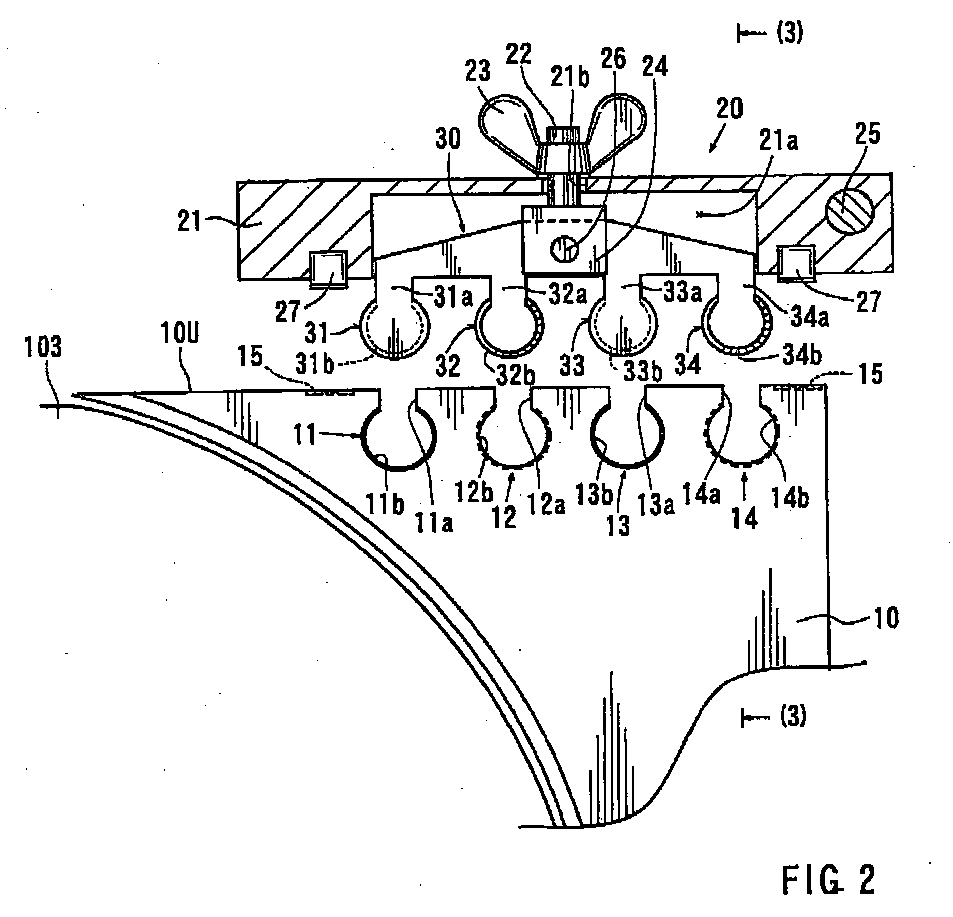
[0125] The first representative embodiment will be initially described with reference to FIGS. 1 to 5. Referring to FIG. 1, a riving knife 10 is positioned within the same plane as a circular saw blade or cutting blade 103. The riving knife 10 is disposed so as to follow the cutting blade 103 with respect to a cutting direction. The cutting blade 103 has an upper portion that extends above the surface of a table 102. The vertical position of the cutting blade 103 and the riving kite 10 may be adjusted with respect to the table 102 in order to change the cutting depth of the cutting blade 103 with respect to a workpiece. In this representative embodiment, the riving knife 10 has a thickness of about 2.0 mm.

[0126] Similar to the cutting blade 103, the riving knife 10 is positioned such that an upper portion of the riving wife 10 extends above the table 102. The riving knife 10 may enter the split formed in the workpiece during the cutting operation so that the width of the split may ...

second representative embodiment

[0147] The second representative embodiment will now be described with reference to FIGS. 6 to 10. This representative embodiment is a modification of the first representative embodiment. Therefore, like members are given the same reference numerals as the first representative embodiment and an explanation of these members may not be repeated. With this second representative embodiment, the cover C can be easily removed from and mounted to a riving knife 40. Similar to the first representative embodiment the cover C may be mounted to the upper portion of the riving knife 40 by a support device 50. In addition, in order to open and close the cover C, the cover C is vertically pivotable about a support shaft 55 mounted to the support device 50.

[0148] The support device 50 includes a support bracket 51 that has a horizontal portion 51a (to the left in FIG. 6) and a vertical portion 51b (to the right in FIG. 6) respectively opposing to an upper end surface 40U and a rear end surface 40...

third representative embodiment

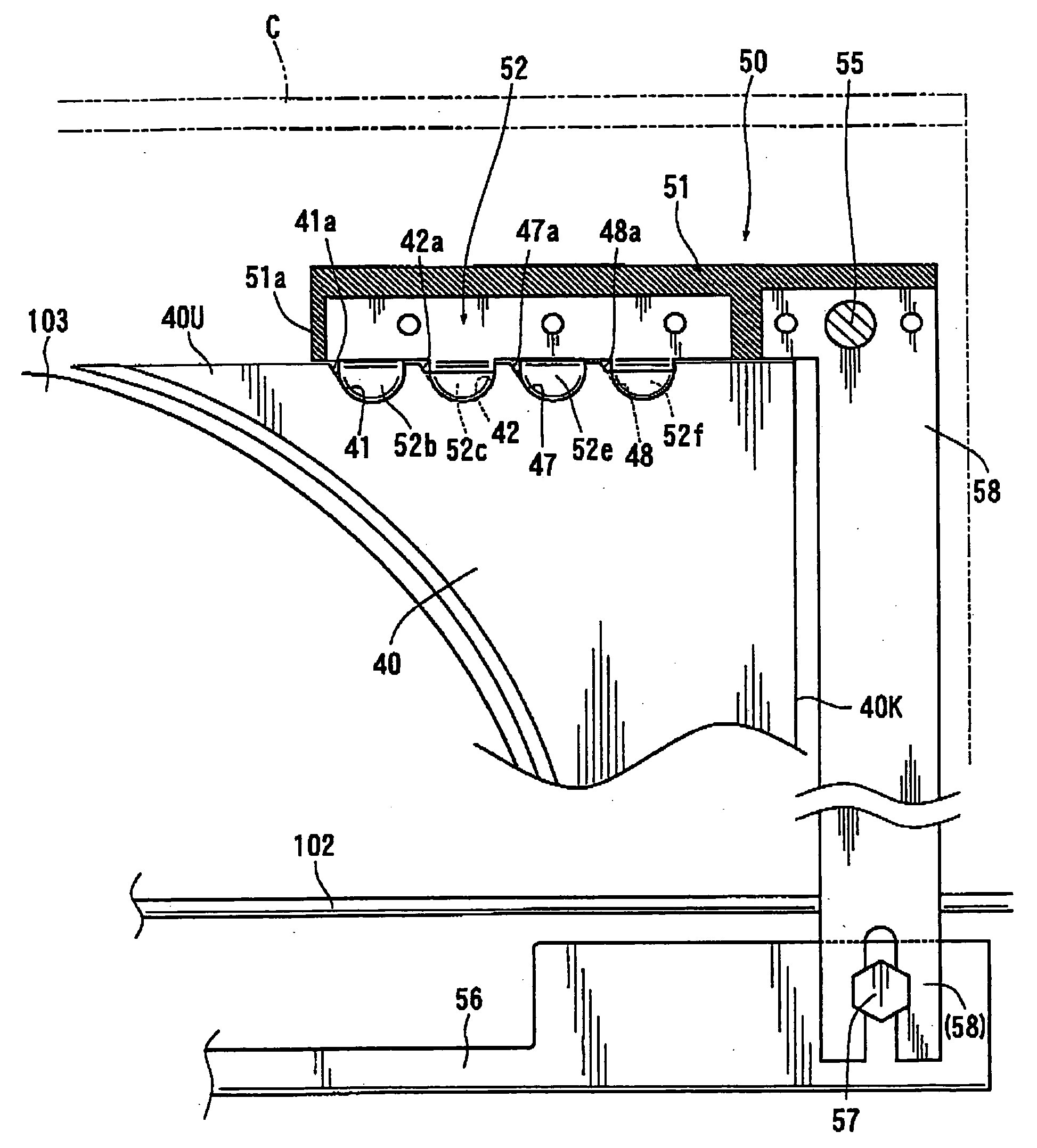
[0166] In the third representative embodiment, as shown in FIG. 11, the vertical portion 51b of the support bracket 51 is replaced with a vertical extension 58 that extends downward below the table 102. The lower and of the vertical extension 58 is fixed in position relative to a mount 56 by a fastening device 57, for example, such as a nut and bolt. The mount 56 is adapted to mount the riving knife 40 thereon. The vertical position of the vertical extension 58 is adjustable relative to the mount 56 via a slot formed in the vertical extension 58, through which a bolt of the fastening device 57 is inserted. In addition, in the third representative embodiment, the movable joint plate 52 is eliminated. Therefore, the joint portions 52b and 52c are directly formed on the horizontal portion 51a of the support bracket 51. Further, two additional joint portions 52e and 52f are also formed on the horizontal potion 51a. As a result, two additional joint recesses 47 and 48, similar to the joi...


PUM

PropertyMeasurementUnit
thicknessaaaaaaaaaa
thicknessaaaaaaaaaa
thicknessaaaaaaaaaa

Abstract

A device for mounting a cover of a cutting blade to a riving knife may have an engaging member for releasably engaging at least a part of the riving knife from both sides, in a direction of thickness of the riving knife. The engaging member is manually operable without any additional tools. A device for mounting a riving knife to a table saw may include a manually operable lock member and a biasing member. The biasing member is arranged and constructed to normally bias the lock member towards a lock position. The riving knife may be divided into a first knife portion and a second knife portion. A positioning device may position the first knife portion and the second knife portion substantially within a single plate.

Description

[0001] This application claims priority to Japanese patent application serial numbers 2004-70679, 2004-74367, and 2004-75584, the contents of which are incorporated herein by reference. BACKGROUND OF THE INVENTION [0002] 1. Field of the Invention [0003] The present invention relates to cutting tools and in particular to cutting tools known as “table saws” having a table and a circular rotary cutting blade, so that a workpiece is cut by the cog blade as it is moved along the table. [0004] 2. Description of the Related Art [0005] Conventionally, as shown in FIGS. 51 and 52, a table saw 100 includes a table 102 for placing a workpiece W thereon, and a circular cutting blade 103 rotatably mounted to the table 102. The cutting blade 103 is positioned such that an upper portion of the cutting blade 103 extends above an upper surface of the table 102. The vertical position of the cutter blade 103 relative to the table 102 can be adjusted in order to adjust the height of the cutter blade 10...

Claims


Application Information

Patent Timeline
Patent Type & Authority Applications(United States)
IPC IPC(8): B23D45/06B23D47/04B27G19/02B27G19/08
CPCB27G19/08B27G19/02Y10T83/2077Y10T83/773Y10T83/7734
Inventor SASAKI, KATSUHIKOSUGIURA, TAKEHIKOINAI, MASAHIKOUCHIDA, MASAAKI
Owner MAKITA CORP
Why Eureka
Try Eureka