Eureka AIR delivers breakthrough ideas for toughest innovation challenges, trusted by R&D personnel around the world.

Low cost truck or like hubcaps

Active Publication Date: 2005-09-29
SKF USA INC
View PDF14 Cites 0 Cited by
  • Summary
  • Abstract
  • Description
  • Claims
  • Application Information

AI Technical Summary

Benefits of technology

[0007] Another object of the invention is to provide a hubcap which lacks the complexity of previous hubcaps, particularly those containing a die-cast stiffener which requires considerable time in the molding cycle.
[0008] Another object of the invention is to provide a hubcap having a simple, stamped and galvanized steel portion which may be used to hold the flange in position.
[0010] A still further object of the invention is to provide a clamping ring or the like which may be provided at the lowest possible cost.
[0011] Another object of the invention is to provide a simple flanged hubcap containing a plurality of retainers, preferably having molded retainers on an outside portion of the hubcap flange.
[0012] A further object of the invention is to provide a series of hubcap flange retainers which will make it difficult for the retainer ring to shift position once it is installed, with the bolt-receiving openings being placed in registry with the openings on the hubcap flange during assembly.
[0013] These and other objects of the present invention are achieved by in practice providing a hubcap having a hubcap body including sidewall and end wall portions, with or without openings in the side walls or end walls, a flange portion, a series of integral small retainers preferably formed on the outside of the flange, and a ring, preferably of stamped and galvanized steel, placed over the flange and secured to the hubcap by plural fasteners, thereby evenly distributing the hold down load.

Problems solved by technology

The disadvantage of the above described method is that the ring requires considerable time in the molding cycle to cool off before becoming integral with the hubcap flange.
This requires time, and although not overly difficult to accomplish, still adds considerable cost to what otherwise would be a simple, moldable part.

Method used


Image

  • Low cost truck or like hubcaps
  • Low cost truck or like hubcaps
  • Low cost truck or like hubcaps

Examples


Embodiment Construction

[0022] Whereas the invention may be practiced in other ways, and other variations will occur to those skilled in the art, a description will now be given of several preferred embodiments of the invention.

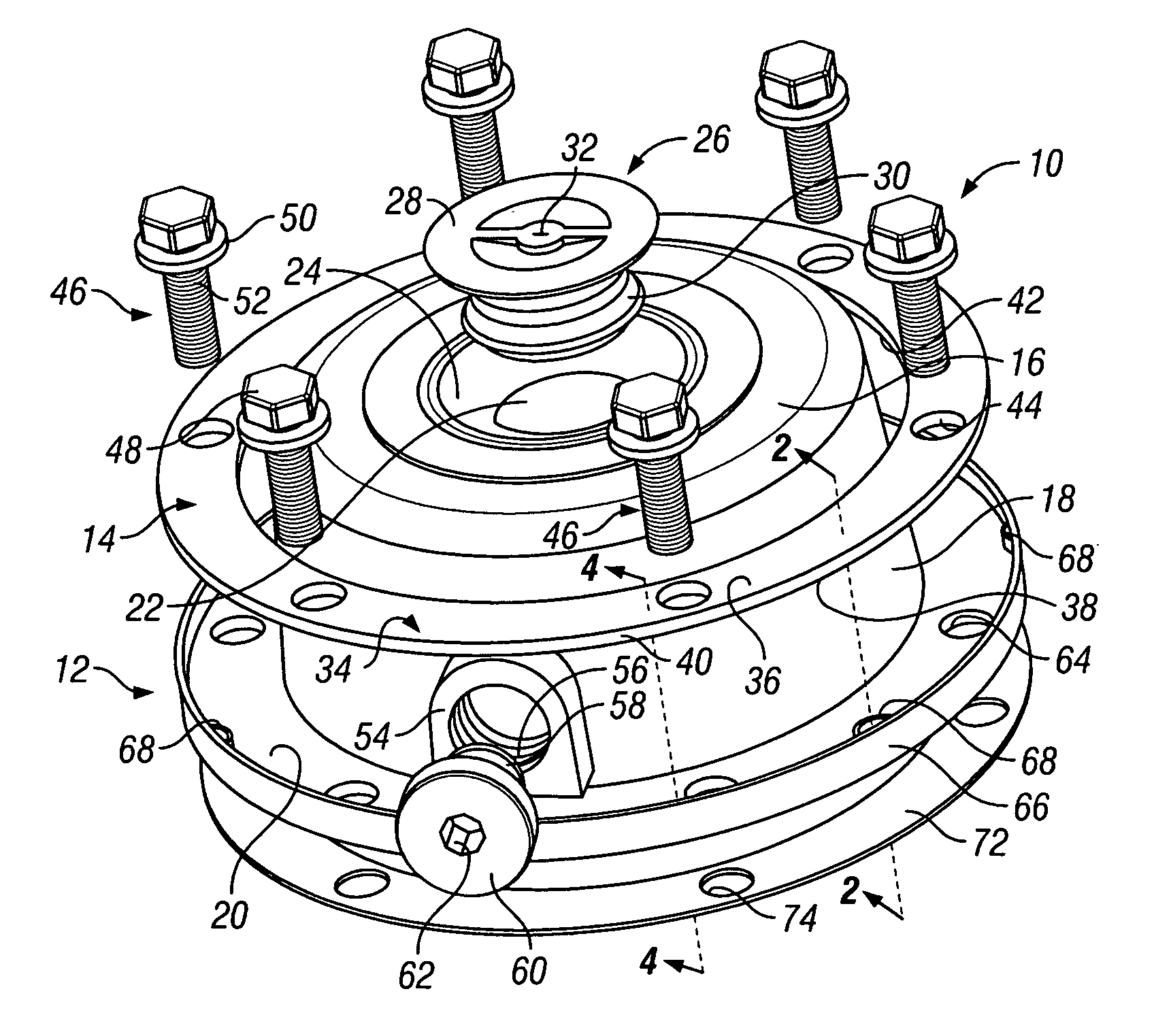
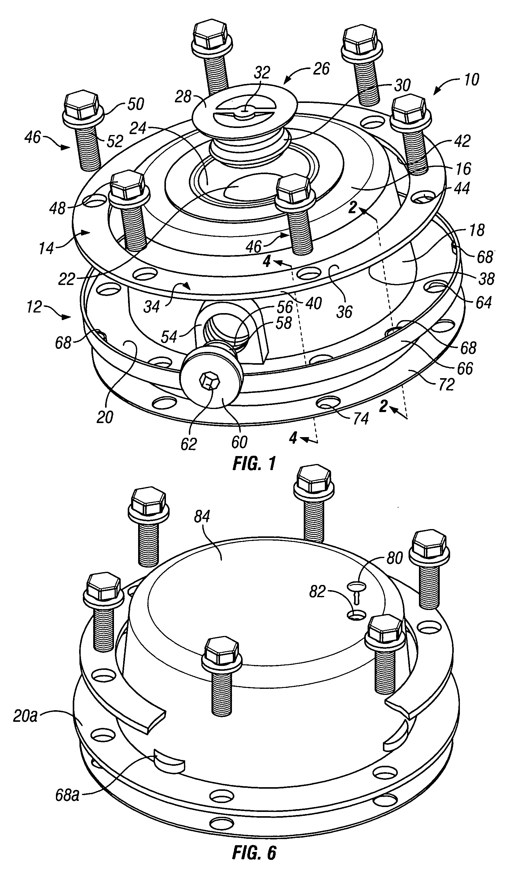
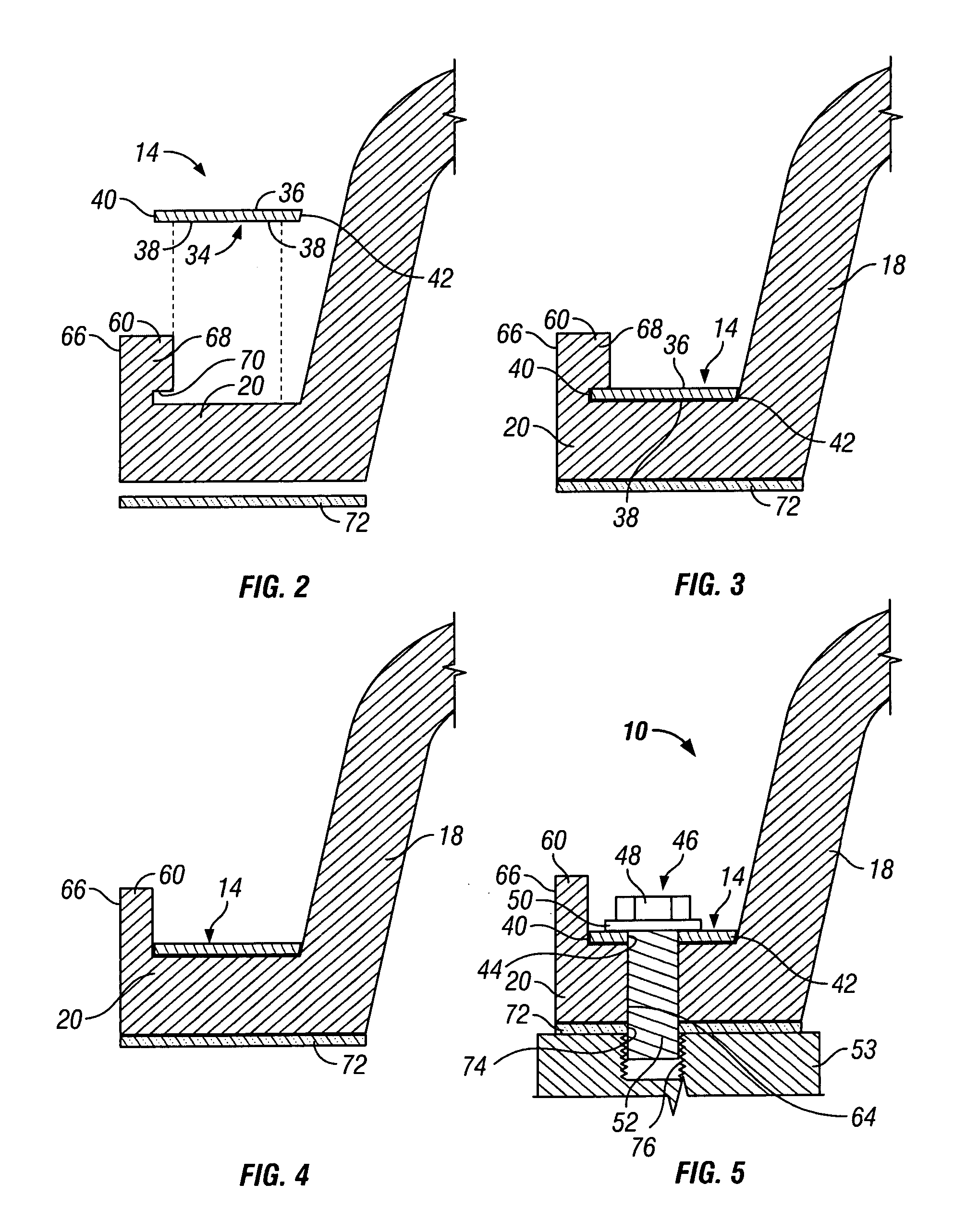
[0023] Referring now to the drawings in greater detail, FIG. 1 shows a hubcap assembly generally designated 10. The hubcap assembly 10 is shown to include a hubcap itself generally designated 12, and a hold down ring generally designated 14. The hubcap 12 includes a circular end wall portion 16, a sidewall portion 18, and a mounting flange 20. The end wall 16 shown has an opening 22, within a tapered inner portion 24, forming a part of the end wall 16. A removable plug generally designated 26 is shown to include an end face portion 28 and a contoured side wall portion 30, as well as a vent portion 32 in the end portion 28 of the plug 26.

[0024] The contoured side wall 30 of the plug 26 fits snugly within the space defined by the tapered portion 24 of the end wall 16 and the opening...


PUM


Abstract

The hub cap has first end wall portion, a sidewall portion and a laterally extending mounting flange. There are plural fastener-receiving openings in the flange. A second endwall portion is integrally formed on the flange and is free from engagement with the hold-down ring. The second end wall portion has a plurality of integral retainers of reduced diameter with respect to the remainder of the wall. There is a hold down ring made from a stiff metal material, overlying the flange on the hub cap. The hold down ring has plural fastener-receiving openings therein, and the retainers snugly secure the hold-down ring in its installed position.

Description

BACKGROUND OF THE INVENTION [0001] The present invention relates generally to hubcaps for trucks or other large vehicles, and more particularly, to hubcaps having a number of novel features. [0002] The present invention is applicable, not only to plastic hubcaps which do not contain any openings, but also to hubcaps which include one or more openings for adding lubricant or checking lubricant within the sealed cavities, opening for pressure venting, etc. [0003] In the past, hubcaps have proven successful which have used an embedded, die-cast ring, preferably of die-cast aluminum, as a part of the flange by which the hub cap is secured. [0004] Such hubcaps, for example, include a flange with plural holes, but also the flange contains an insert of a relatively complex configuration which is preferably made by die casting. Such an insert contains increased height portions surrounding the bolt holes, spaced apart by a portion of less height between them. Consequently, the portion defini...

Claims


Application Information

Patent Timeline
IPC IPC(8): B60B7/00B60B7/14B60B27/00
CPCB60B7/14
Inventor DENTON, DENNIS N.
Owner SKF USA INC
Why Eureka
Eureka Blog
Learn More