Methods and apparatus for position estimation using reflected light sources

a technology of reflected light and method, applied in the direction of distance measurement, reradiation, instruments, etc., can solve the problems of inability to detect the emitter, disadvantageous constraints, and optical beacons paired with optical sensors

Inactive Publication Date: 2005-09-29
IROBOT CORP
View PDF17 Cites 352 Cited by
  • Summary
  • Abstract
  • Description
  • Claims
  • Application Information

AI Technical Summary

Problems solved by technology

These approaches, which use active optical beacons paired with optical sensors, are disadvantageously constrained by line-of-sight between the emitters and the sensors.
Without line-of-sight, a sensor will not be able to detect the emitter.

Method used


Image

  • Methods and apparatus for position estimation using reflected light sources
  • Methods and apparatus for position estimation using reflected light sources
  • Methods and apparatus for position estimation using reflected light sources

Examples


Embodiment Construction

[0027] Although these methods and apparatus will be described in terms of certain preferred embodiments, other embodiments that are apparent to those of ordinary skill in the art, including embodiments that do not provide all of the benefits and features set forth herein, are also within the scope of the invention

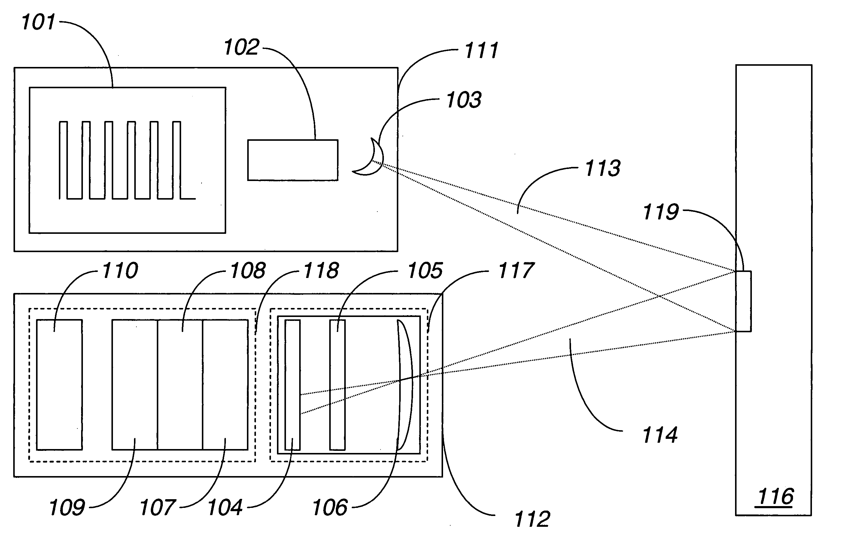
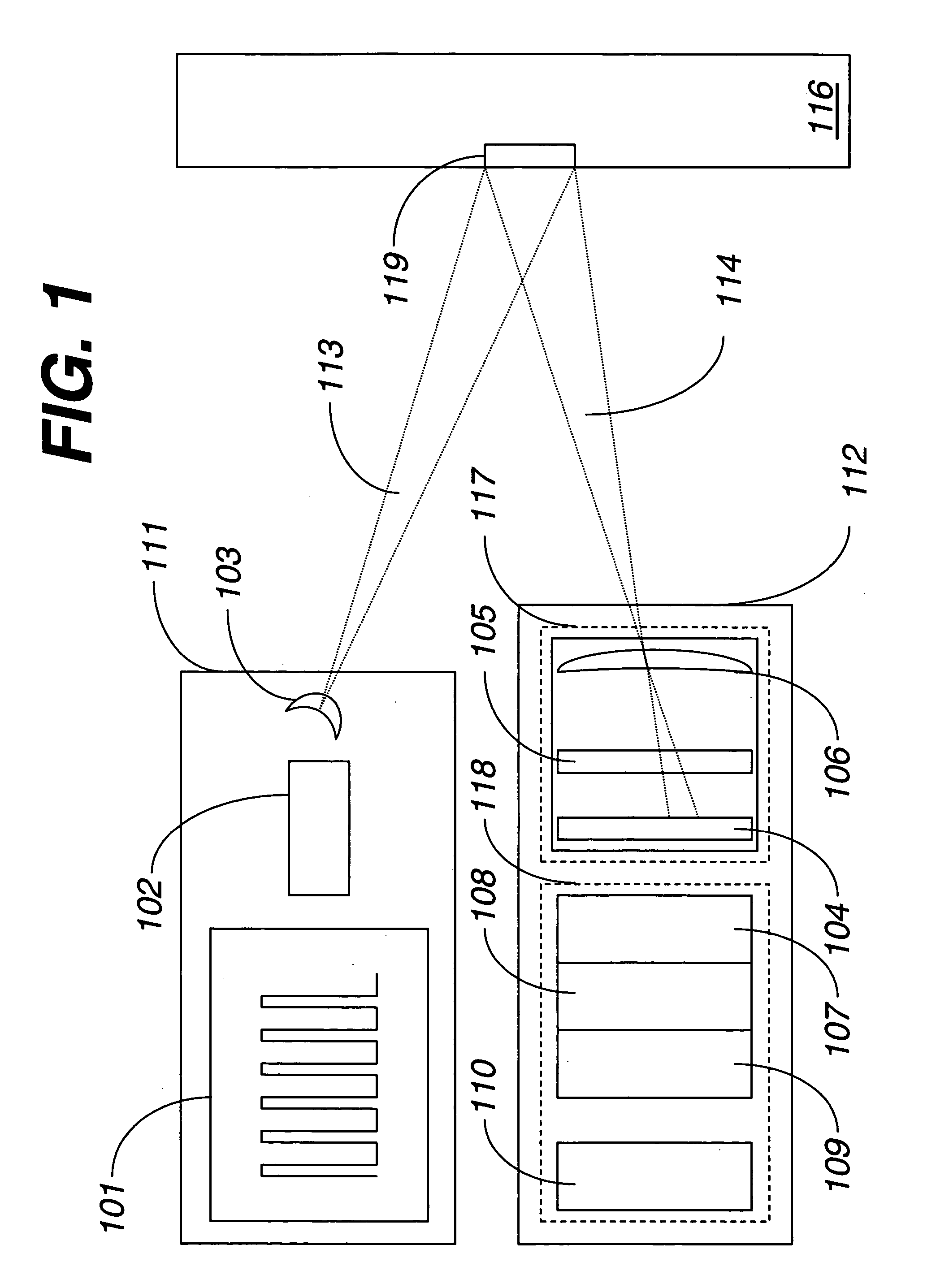
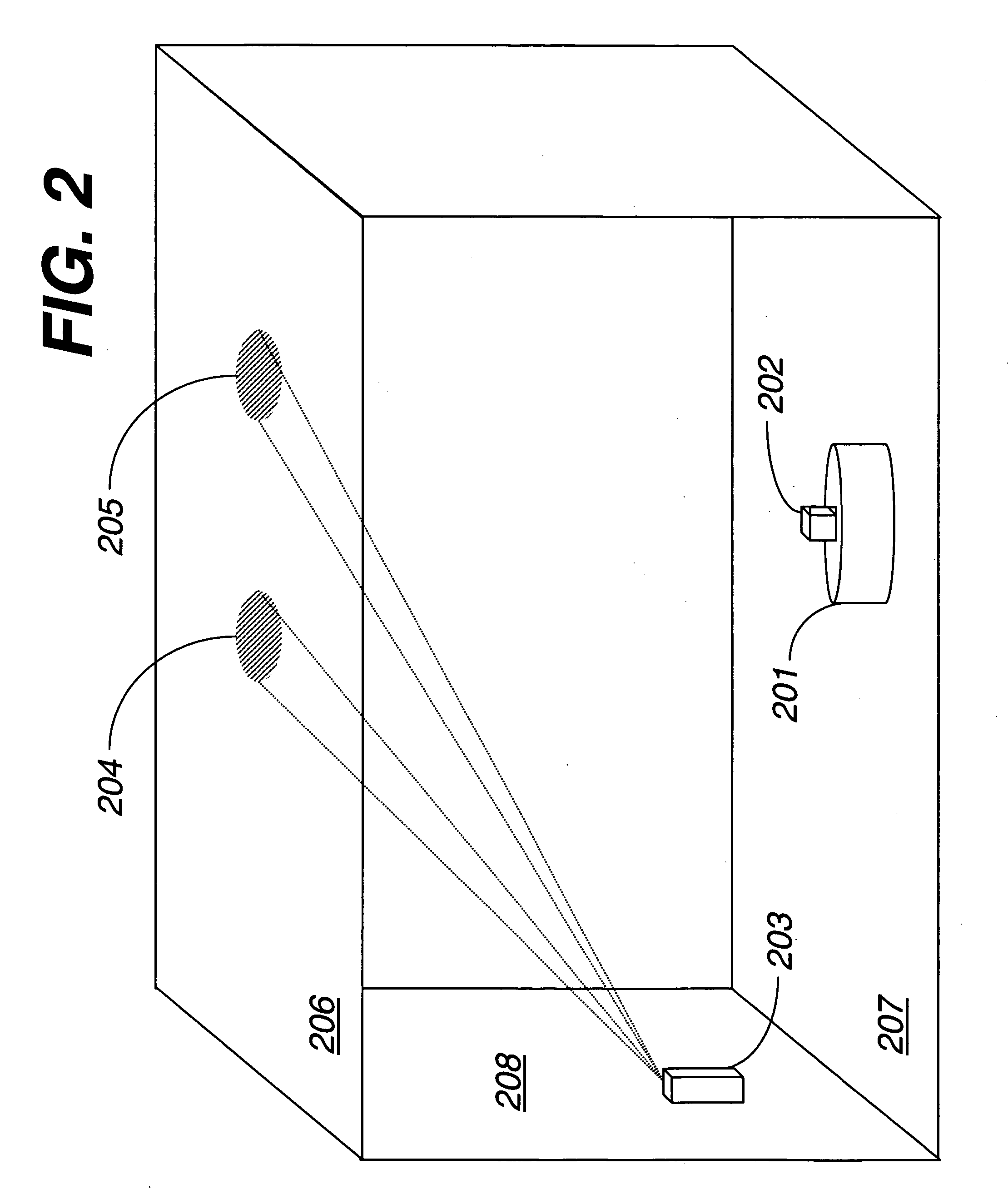
[0028] Embodiments advantageously use active optical beacons in position estimation. Advantageously, disclosed techniques minimize or reduce the line-of-sight limitation of conventional active optical beacon-based localization by projecting the light sources onto a surface that is observable from a relatively large portion of the environment. It will be understood that the light sources can include sources of light that are not visible to the naked eye, such as, for example, infrared (IR) sources. For example, in an indoor environment, it can be advantageous to project the emitted light from the beacon onto the ceiling. In many indoor environments, the ceiling of a room is...


PUM


Abstract

The invention is generally related to the estimation of position and orientation of an object with respect to a local or a global coordinate system using reflected light sources. A typical application of the method and apparatus includes estimation and tracking of the position of a mobile autonomous robot. Other applications include estimation and tracking of an object for position-aware, ubiquitous devices. Additional applications include tracking of the positions of people or pets in an indoor environment. The methods and apparatus comprise one or more optical emitters, one or more optical sensors, signal processing circuitry, and signal processing methods to determine the position and orientation of at least one of the optical sensors based at least in part on the detection of the signal of one or more emitted light sources reflected from a surface.

Description

RELATED APPLICATION [0001] This application claims the benefit under 35 U.S.C. § 119(e) of U.S. Provisional Application No. 60 / 557,252, filed Mar. 29, 2004, the entirety of which is hereby incorporated by reference. APPENDIX A [0002] Appendix A, which forms a part of this disclosure, is a list of commonly owned co-pending U.S. patent applications. Each one of the co-pending applications listed in Appendix A is hereby incorporated herein in its entirety by reference thereto.BACKGROUND OF THE INVENTION [0003] 1. Field of the Invention [0004] This invention generally relates to the estimation of position and orientation of an object with respect to a local or a global coordinate system. In particular, the invention relates to the method and apparatus that provides estimation and tracking of the position and orientation. The method and apparatus that can be used in vehicles, such as in mobile robots. [0005] 2. Description of the Related Art [0006] Position estimation is a topic of inter...

Claims


Application Information

Patent Timeline
Patent Type & Authority Applications(United States)
IPC IPC(8): G01C3/00G01C3/08G01C5/00G01S5/16G01S17/06G01S17/48G05D1/02
CPCG01S5/163G01S17/06G01B11/002G01C3/06G01S17/48G05D1/0234
Inventor DIBERNARDO, ENRICOPIRJANIAN, PAOLO
Owner IROBOT CORP
Why Eureka
Try Eureka