Light-Guiding structure for floor-pan edge of a car

Inactive Publication Date: 2005-09-29
YANG CHANG AN
View PDF5 Cites 77 Cited by
  • Summary
  • Abstract
  • Description
  • Claims
  • Application Information

AI Technical Summary

Benefits of technology

[0007] An object of the present invention is to provide a light-guiding structure for floor-pan edge of a car, wherein a minimum lig

Problems solved by technology

The cost of material is higher than that used in cold lig

Method used


Image

  • Light-Guiding structure for floor-pan edge of a car
  • Light-Guiding structure for floor-pan edge of a car
  • Light-Guiding structure for floor-pan edge of a car

Examples


Embodiment Construction

[0016] The following descriptions are of exemplary embodiments only, and are not intended to limit the scope, applicability or configuration of the invention in any way. Rather, the following description provides a convenient illustration for implementing exemplary embodiments of the invention. Various changes to the described embodiments may be made in the function and arrangement of the elements described without departing from the scope of the invention as set forth in the appended claims.

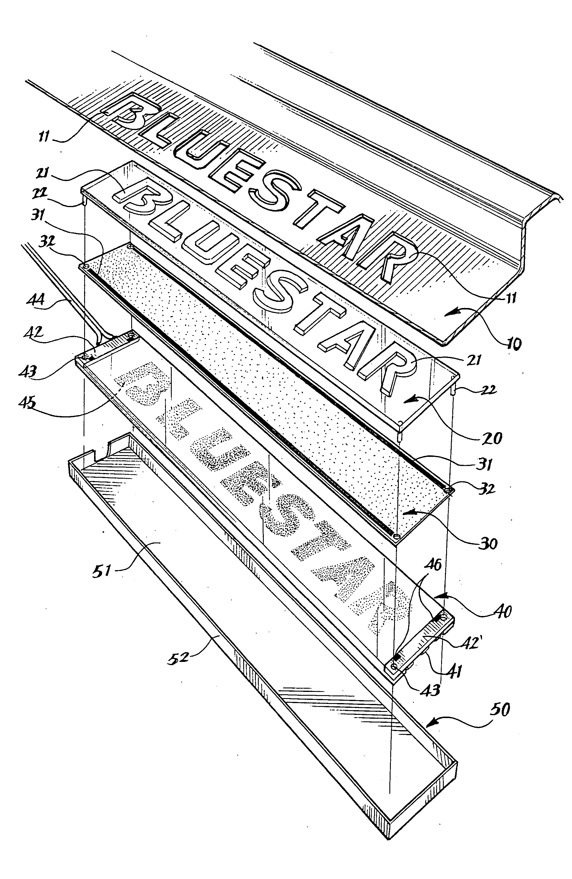
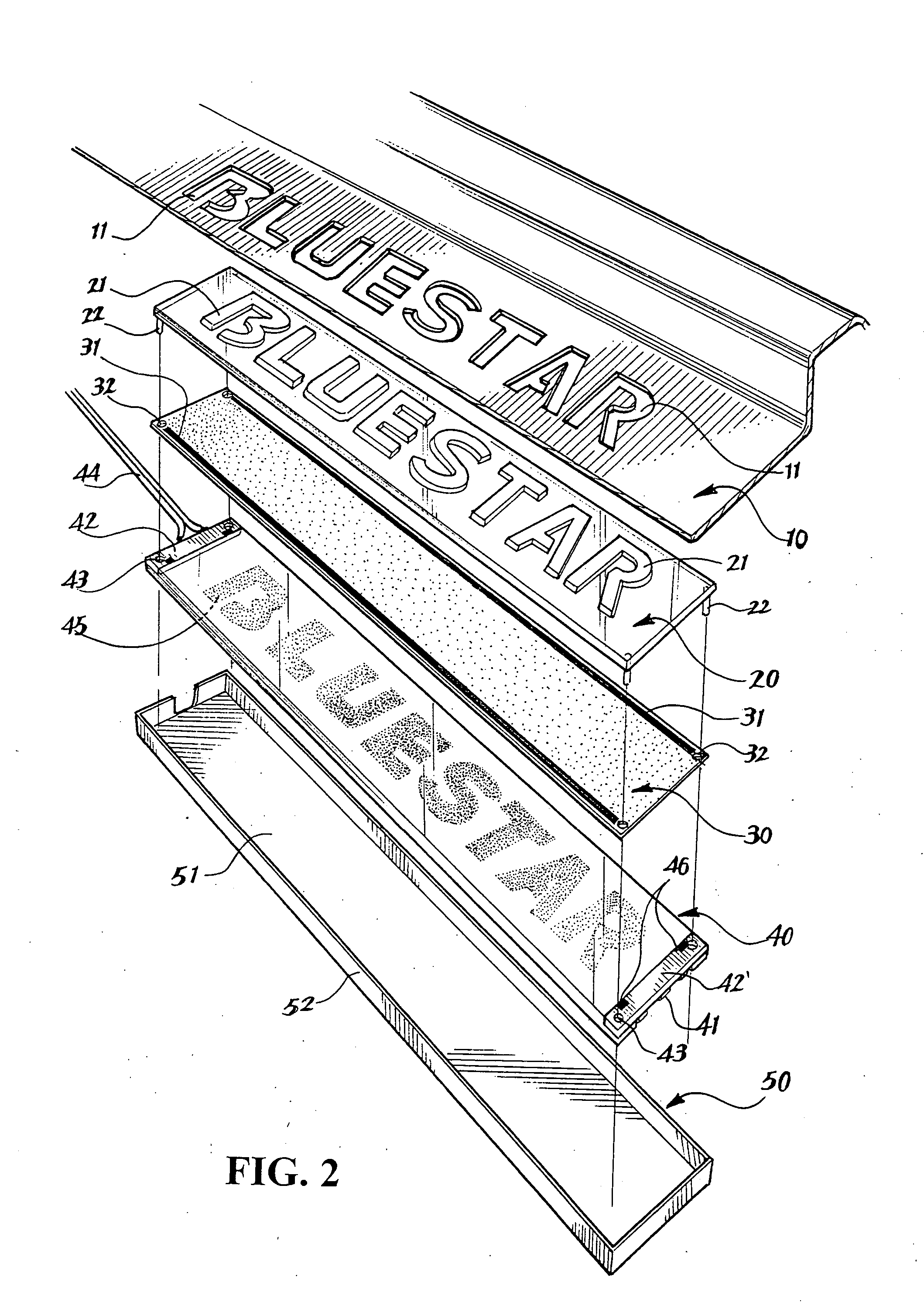
[0017] Referring to FIGS. 2 and 3, there is shown a light-guiding structure for floor-pan edge of a car comprising an opaque plate 10 with through hole 11 having characters, a transparent plate 20 with embossed characters 21, a disperse film 30 mounted with conductive material 31, a light-guiding plate 40 having two ends mounted with a plurality of LEDs 41 as light sources 42, 42′ and having a light reflective matte surface 45 with a bottom section corresponding to character used as a water res...


PUM


Abstract

A light-guiding structure for floor-pan edge of a car is disclosed. A LED is used as the light source to project light source at the two ends of the elongated thin light-guiding plate. The bottom section of the light-guiding material is provided with a reflective matte surface which can focus and reflect light. The reflective matte surface corresponds to each separate embossed character on the transparent plate surface which respectively refracts the reflected light so that the reflected light is focus on the surface of the embossed character. This will provide stronger light with the lesser light source as an ornamental to the floor-pan edge of a car.

Description

BACKGROUND OF THE INVENTION [0001] (a) Technical Field of the Invention [0002] The present invention relates to a floor-pad edge light-guiding plate, and in particular to a light-guiding structure employing micro LED as light source to project light source at the two ends of the elongated thin light-guiding plate. The bottom section of the light-guiding material is provided with a reflective matte surface which can focus and reflect light. The reflective matte surface corresponds to each separate embossed character on the transparent plate surface which respectively refracts the reflected light so that the reflected light is focus on the surface of the embossed character. This will provide stronger light with lesser light source as an ornamental to the floor-pan edge of a car. [0003] (b) Description of the Prior Art [0004] Published Patent No. ZL 98225145.9 entitled “EMBOSSED LED STRUCTURE USED IN CAR” discloses the use of cold light as light source for pedal plate for door panel. A...

Claims


Application Information

Patent Timeline
IPC IPC(8): B60Q1/32B60R13/02B60R13/04G01D11/28
CPCB60Q1/323B60R2013/046B60R13/005B60R13/04B60Q1/325
Inventor YANG, CHANG-AN
Owner YANG CHANG AN
Why Eureka
Try Eureka