Fuel cell stack

a fuel cell and stack technology, applied in the field of fuel cell stacks, can solve problems such as poor productivity, and achieve the effect of further improving sealing performance relative to the pressing surfa

Active Publication Date: 2005-09-29
HONDA MOTOR CO LTD
View PDF1 Cites 30 Cited by
  • Summary
  • Abstract
  • Description
  • Claims
  • Application Information

AI Technical Summary

Benefits of technology

[0028] With this structure, the followingness of the packing relative to the pressing surface when the packing is deforme

Problems solved by technology

However, providing an individual waterproofing member for each of the large number of terminals that is

Method used


Image

  • Fuel cell stack
  • Fuel cell stack
  • Fuel cell stack

Examples


Embodiment Construction

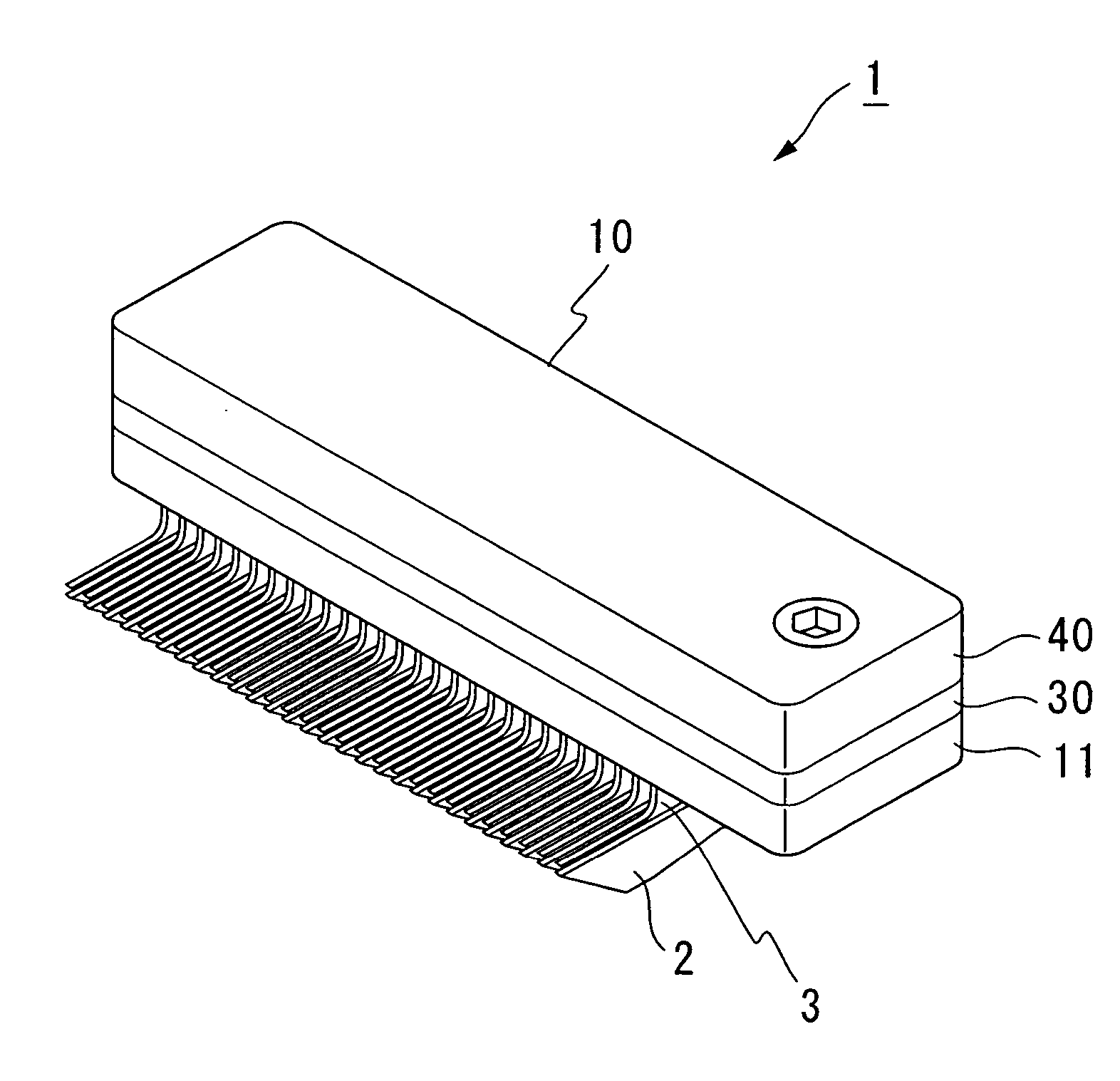
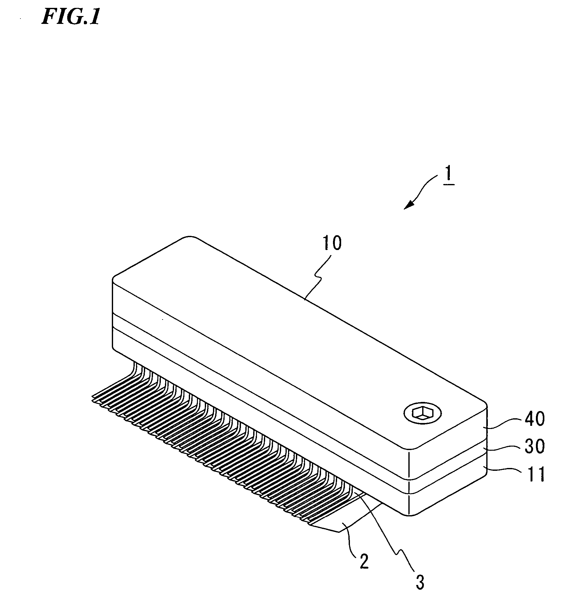
[0051] The first embodiment of the fuel cell stack of the present invention will now be described with reference made to the drawings of FIGS. 1 through 10.

[0052] As is shown in FIG. 1, a fuel cell stack 1 is formed by stacking a plurality of separators 2 that sandwich membrane electrode structures (not shown) inside a stack housing (not shown). The fuel cell stack 1 is also provided with a connector unit that measures a voltage between adjacent separators 2 and 2.

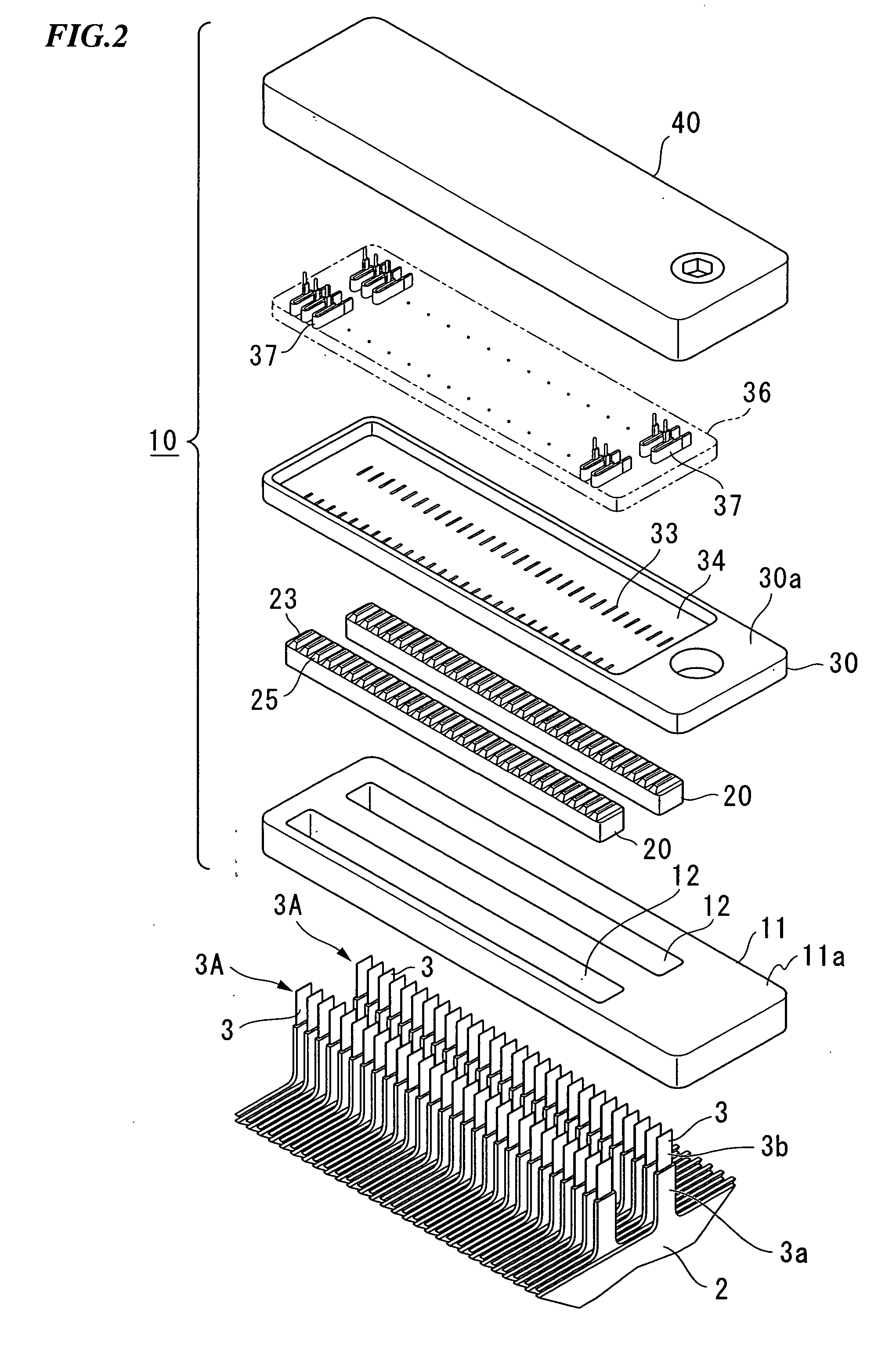
[0053] As is shown in FIG. 2, the separators 2 are provided with plate-shaped terminals 3 that extend upwards from a top end portion of the separators 2. In a state in which the separators 2 are stacked, the placement positions of the terminals 3 are offset from each other in adjacent separators 2 and 2. As a result, two columns of terminal groups 3A and 3A are formed running in the stacking direction. Base portions 3a of these terminals 3 are coated in resin, while metal surfaces of distal end portions 3b thereof are ex...


PUM


Abstract

A fuel cell stack is provided with a plurality of stacked separators. This fuel cell stack includes: terminals that extend from the separators; packing in which are formed a plurality of through holes through which the terminals are inserted; a packing casing that has a packing housing concave portion that envelops side surfaces of the packing and supports a bottom surface of the packing, and has through holes through which the terminals are inserted; and a connector housing that has a pressing surface that presses a top surface of the packing. Mountain-shaped protruding portions whose apex portions are formed by circumferential edges of apertures of the respective through holes are provided on the top surface of the packing, and the pressing surfaces of the connector housing are formed in a configuration that conforms to the side surfaces of the protruding portions. Internal surfaces of the through holes in the packing are in contact without a gap in between with external surfaces of the terminals. The sealing performance in extraction portions of terminals that are used for cell voltage detection is improved.

Description

BACKGROUND OF THE INVENTION [0001] 1. Field of the Invention [0002] The present invention relates to a fuel cell stack, and particularly to a waterproof structure that surrounds terminals used for voltage measurement in each cell. [0003] Priority is claimed on Japanese Patent Application No. 2004-76448, filed Mar. 17, 2004, and No. 2004-200312, filed Jul. 7, 2004, the contents of which are incorporated herein by reference. [0004] 2. Description of Related Art [0005] Among fuel cells that are mounted in a fuel cell vehicle or the like, there are those in which a solid polymer electrolyte membrane is sandwiched between an anode electrode and a cathode electrode so as to form a membrane electrode structure. This membrane electrode structure is sandwiched between a pair of separators so as to form a cell (i.e., a unit fuel cell). In this type of fuel cell, typically, a plurality of cells are stacked and used as a fuel cell stack. [0006] In this fuel cell, if fuel gas (for example, hydro...

Claims


Application Information

Patent Timeline
IPC IPC(8): G11C7/00H01M8/02H01M8/04H01M8/10H01M8/24H01M50/529
CPCH01M8/0247H01M8/0273H01M8/0276H01M8/2475Y02T90/32H01M2008/1095H01M2250/20Y02E60/50H01M8/248Y02T90/40H01M8/24
Inventor WAKAHOI, TOSHIYAKAWASE, NAOKAZUHIDAKA, YOHEI
Owner HONDA MOTOR CO LTD
Why Eureka
Try Eureka