Power line communication system and method

a communication system and power line technology, applied in the direction of electric controllers, ignition automatic control, instruments, etc., can solve the problems of poor high frequency impedance characteristics, insufficient broadband internet infrastructure, and difficulty in overcoming them, so as to facilitate the transmission and reception of data signals and maximize the flux linkage

Inactive Publication Date: 2005-09-29
CURRENT TECH
View PDF99 Cites 56 Cited by
  • Summary
  • Abstract
  • Description
  • Claims
  • Application Information

AI Technical Summary

Benefits of technology

[0031] It is a further object of the present invention to provide a power line coupler device that is self-contained and is nearly impervious to environmental conditions.
[0034] It is still another object of the present invention to provide a non-intrusive power line coupler device with a hinged power line coupler for ease of installation.
[0037] The data signals are coupled on to and off of the power line with a power line coupler (PLC) device. One embodiment of the present invention uses an inductive method to couple and de-couple data signals off of the power line. A toroid with conductive windings is placed around the power line. This method effectively provides a transformer between the power line and the PLC device circuitry thus facilitating the transmission and receiving of the data signal. For the primary side of the transformer, the number of windings and the orientation of the windings around the magnetic toroid is guided by the desire to maximize the flux linkage.
[0039] Since communications signals are very high frequency, a step down transformer would filter a signal coupled on the power line. The system to which present invention is a component avoids filtering of high frequency signals by bypassing the transformer with a power line bridge (PLB). The PLB, using a PLC device, de-couples data signals from the medium (MV) or high voltage (HV) line a short distance from a transformer. The PLB interfaces between the power line on the primary of the transformer and the low voltage (LV) line on the secondary of the transformer. (The primary is the side of the transformer where the relatively high voltage enters; the secondary is the side of the transformer where the stepped down, lower voltage exits the transformer.)
[0044] The light signal is converted back to an electronic signal and then coupled onto the LV power line (LV coupler). In an embodiment of the present invention a second isolator is inserted in the system between the second modem and the data router for conversion of the light signal to electrical signal. Additionally the isolator proves an additional layer of safety because of the dielectric quality of the second isolator.

Problems solved by technology

The infrastructure for providing broadband Internet access is presently insufficient to meet demand.
Of course, there are a series of problems to be overcome before a PDS can be used as an efficient, high-speed power line communications medium.
For any method developed, a significant challenge lies in being able to mitigate the adverse effects of the high voltage 50-60 Hz power signal might have on the communications signal.
Whyte, et al. in U.S. Pat. No. 4,142,178 observe: “The use of the distribution network conductors for the transmission of carrier communication signals presents many problems not encountered in high voltage transmission line communication systems.
Some of these problems include the poor high frequency impedance characteristics and the high level of electrical noise present on the distribution network conductors which, along with the plurality of distribution transformers and power factor correction capacitors attached to the distribution network, rapidly attenuate the communication signals.”
Those functions are still desirable, but the function of high speed, high bandwidth communication transmission preclude direct connection from a transformer to remote data terminals economically.

Method used


Image

  • Power line communication system and method
  • Power line communication system and method
  • Power line communication system and method

Examples


Embodiment Construction

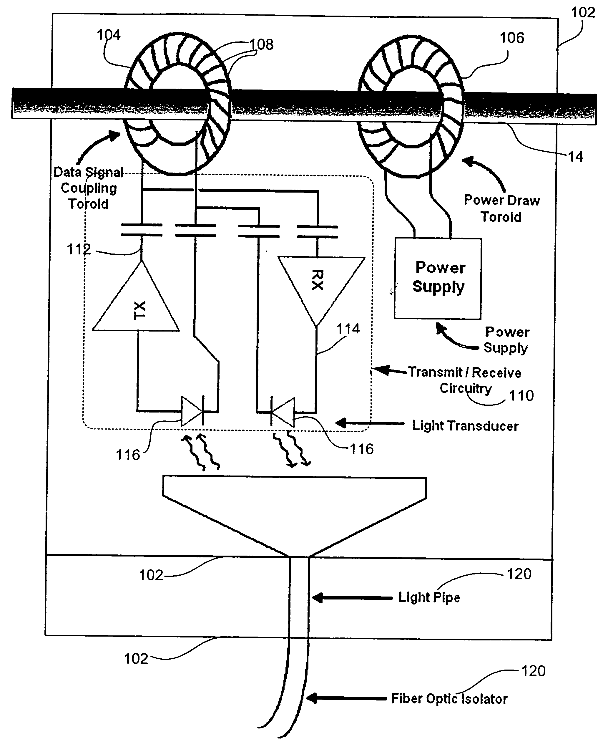
[0052] The present invention is a power line coupler device specially suited for coupling and de-coupling high frequency, broadband signals carried over power lines within a power distribution system. The PLC device includes the coupler and circuitry necessary to condition the signal, to handle bi-directional signal transfer, to enable the use of an isolator, to be self-contained and to be able to provide operational power from the power line. The PLC device is part of an overall power line communication system (PLCS) which incorporates the present invention and other, companion inventions from the same inventor. The following description is a description of the PLCS in general. The PLC device embodiment is included in the system description. The description pertinent to the PLC device should be apparent to one skilled in the art.

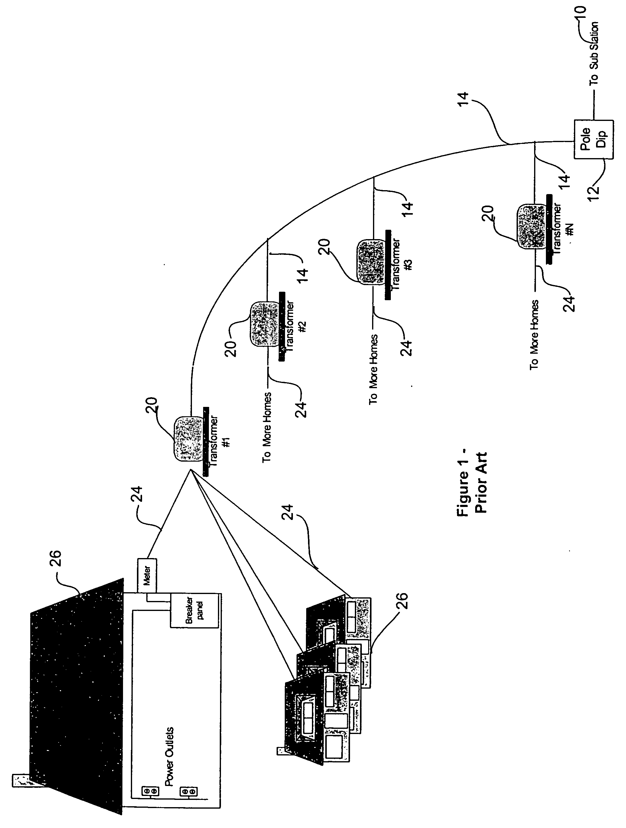
[0053] Referring to FIG. 1, the typical electric distribution topology of the prior art is illustrated. Medium voltage (MV) half loop power delivery syste...


PUM


Abstract

The present invention is drawn to an electrically “closed” method and apparatus for transmitting and receiving data signals over a high voltage power line. Inductive coupling is employed for coupling and decoupling the data signal directly on to and off of a single power line wire. An exemplary device includes a high frequency inductive coupling toroid for data signals, a second (50-60 Hz) inductive coupling toroid for providing power, signal conditioning electronics for the receive and transmit signal, a fiber optics interface for electrical isolation purposes, and a weather-proof enclosure. In a preferred embodiment, the toroids are hinged for ease of installation on a power line. A pair of such couplings on either side of a fiber-optic isolator can be used to bridge transformers.

Description

CROSS REFERENCE TO RELATED APPLICATIONS [0001] This application claims priority under 35 U.S.C. § 119(e) from provisional application No. 60 / 268,578, filed Feb. 14, 2001. The 60 / 268,578 provisional application is incorporated by reference herein, in its entirety, for all purposes.FIELD OF THE INVENTION [0002] The present invention is concerned with the field of transmitting and receiving high frequency, high bandwidth signals safely and efficiently over power lines. An exemplary system comprises a power line coupler of the present invention, a fiber optic isolator and a communications interface to various media. More specifically, the present invention is drawn to a method and apparatus for coupling to a high voltage power line for transmitting and receiving high frequency, high bandwidth signals.BACKGROUND [0003] With well-established power distribution systems (PDSs) already in place throughout much of the world, an efficient power line communication system (PLCS) could provide mo...

Claims


Application Information

Patent Timeline
Patent Type & Authority Applications(United States)
IPC IPC(8): H02G11/02H04B3/56
CPCH02G11/02H04B2203/5487H04B3/56
Inventor KLINE, PAUL A.
Owner CURRENT TECH
Why Eureka
Try Eureka