Adjustable optical apparatus adapter

Active Publication Date: 2005-09-29
LONGPERNG
8 Cites 23 Cited by

AI-Extracted Technical Summary

Problems solved by technology

Due to limited amplification, it is difficult to ...

Benefits of technology

[0006] The present invention has been accomplished under the circumstances in view. It is therefore one object of the present invention to provide an adjustable optical apparatus adapter, which can be adjusted to couple a telescope to a camera in an axially aligned status. It is anther object of the present...

Abstract

An adjustable optical apparatus adapter is disclosed to include a camera platform provided with a mounting screw and a wing nut for securing a camera to the camera platform, a telescope holder for holding a telescope, a holding down frame controlled by a lock screw to hold down a telescope in the telescope holder, and a camera platform lock mounted in the a horizontal sliding slot in camera platform and a vertical sliding slot in telescope holder for locking the camera platform to the telescope holder after position adjustment of the camera platform horizontally and vertically relative to the telescope holder to have the loaded telescope at the telescope holder in axial alignment with the loaded camera at the camera platform.

Application Domain

Technology Topic

Image

  • Adjustable optical apparatus adapter
  • Adjustable optical apparatus adapter
  • Adjustable optical apparatus adapter

Examples

  • Experimental program(1)

Example

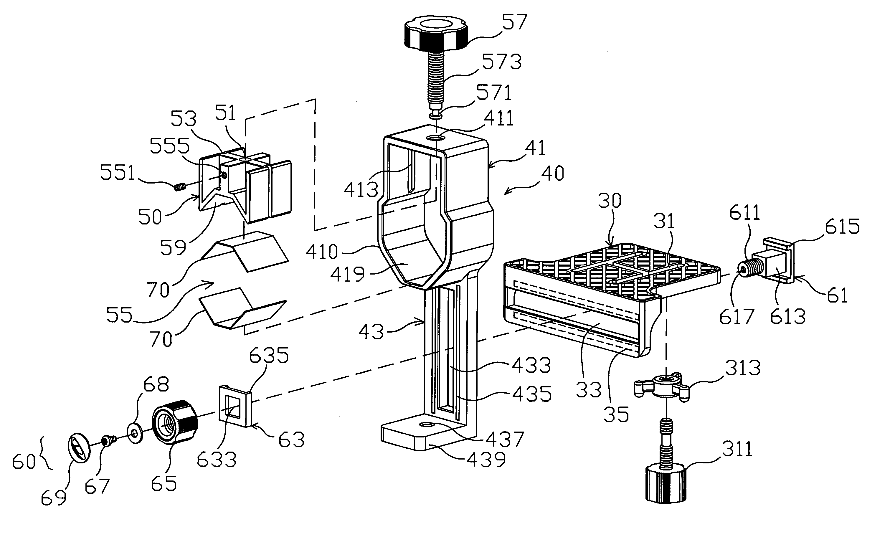
[0021] Referring to FIGS. 2A, 2B, 3A, and 3B, an adjustable optical apparatus adapter in accordance with one embodiment of the present invention is shown comprised of a camera platform 30, a telescope holder 40, a holding down frame 50, and a camera platform lock 60.
[0022] The camera platform 30 comprises at least one vertical slot 31 cut through the top and bottom walls thereof, a horizontal sliding slot 33 in one vertical sidewall thereof, and two horizontal sliding grooves 35 arranged in parallel at two sides along the horizontal sliding slot 33. Further, a mounting screw 311 is threaded into a wind nut 313 and inserted through the at last one vertical slot 31 to fix a photographic apparatus, for example, a camera 83 to the camera platform 30.
[0023] The telescope holder 40 has an upper part 41 and a lower part 43. The upper part 41 comprises a holder frame 410, a top screw hole 411 vertically formed in the top side of the holder frame 410, and at least one, for example, two coupling rails 413 formed integral with the inside wall of the holder frame 410 at two sides. The lower part 43 comprises a vertical sliding slot 433, two vertical sliding grooves 435 arranged in parallel at two sides of the vertical sliding slot 433, a bottom mounting plate 439, and a screw hole 437 vertically formed in the bottom mounting plate 439.
[0024] The holding down frame 50 comprises a top mounting hole 51, at least one, for example, two coupling grooves 53 symmetrically disposed at two opposite lateral sides corresponding to the coupling rails 413 of the telescope holder 40, and a front screw hole 555 in communication with the top mounting hole 51.
[0025] The camera platform lock 60 is comprised of a base block 61, a slide 63, and a locknut 65. The base block 61 comprises at least one, for example, two horizontal coupling flanges 615 arranged in parallel at the front side and respectively coupled to the horizontal sliding grooves 35 of the camera platform 30, a rectangular shoulder 613 forwardly extended from the front side and inserted into the horizontal sliding slot 33 of the camera platform 30, a front screw rod 611 axially forwardly extended from the rectangular shoulder 613 and inserted through the vertical sliding slot 433 of the telescope holder 40, and a screw hole 617 axially formed in the front end of the front screw rod 611. The slide 63 has a center opening 633 fitting the cross section of the rectangular shoulder 613 of the base block 61, and two coupling flanges 635 arranged in parallel at two sides of the center opening 633 and respectively coupled to the vertical sliding grooves 435 of the telescope holder 40. The locknut 65 is threaded onto the front screw rod 611 to lock the camera platform 30 to the telescope holder 40 at the desired elevation.
[0026] After installation of the a mounting screw 311 in one vertical slot 31 of the camera platform 30 to fix a camera 83 to the camera platform 30, the user can turn the wind nut 313 to lock/unlock the camera 83. Further, the user can move the mounting screw 311 in the at least one vertical slot 31 to the desired location subject to the model of the photographic apparatus to be used. Therefore, the camera platform 30 can hold any of a variety of cameras.
[0027] After coupling of the coupling grooves 53 of the holding down frame 50 to the coupling rails 413 of the telescope holder 40, a holding down frame 50 define with the holder frame 410 a clamping hole 55 for holding down a telescope 80.
[0028] A lock screw 57 is provided to move the holding down frame 50 in the telescope holder 40, and to further adjust the size of the clamping hole 55 so as to lock/unlock the telescope 80. The lock screw 57 has a threaded shank 573 threaded into the top screw hole 411 of the holder frame 410 of the telescope holder 40 and inserted into the top mounting hole 51 of the holding down frame 50, and a locating groove 571 extended around the periphery of the front end of the threaded shank 573. A tightening up screw 551 is threaded into the front screw hole 555 of the holding down frame 50 and engaged into the locating groove 571 to fix the holding down frame 50 to the lock screw 57. When rotating the lock screw 57 forwards or backwards in the top screw hole 411 of the holder frame 410, the holding down frame 50 is moved vertically upwards or downwards with the lock screw 57 along the coupling rails 413 of the telescope holder 40 to adjust the size of the clamping hole 55 subject to the size of the telescope 80. Therefore, the telescope holder 40 can hold any of a variety of telescopes. Rubber pads 70 are respectively provided at the bottom wall 59 of the holding down frame 50 and the inner bottom wall 419 of the holder frame 410 to protect the telescope 80 and to prevent slipping of the telescope 80.
[0029] The aforesaid camera platform lock 60 further comprises a screw 67, a washer 68, and an ornamental cap 69. The screw 67 is inserted through the washer 68 and then threaded into the screw hole 617 of the base block 61 to prevent falling of the lock nut 65 from the base block 61. The ornamental cap 69 is capped on the lock nut 65 to keep the screw 67 and the washer 68 from sight. The ornamental cap 69 may be marked with a company's logo or the like.
[0030] Further, by means of the screw hole 437, the bottom mounting plate 439 of the telescope holder 40 can be fastened to the camera platform of a tripod (not shown). After installation of the telescope holder 40 in a tripod, a telescope 80 can be fastened to the telescope holder 40 and firmly held down by the holding down frame 50, and a camera 83 can be affixed to the camera platform 30, keeping the lens of the camera 83 aimed at the eyepiece of the telescope 80.
[0031] Referring to FIGS. 4A and 4B and FIG. 2A again, the rectangular shoulder 613 of the base block 61 fits the horizontal sliding slot 33 of the camera platform 30. Therefore, the base block 61 is prohibited from rotary motion in the horizontal sliding slot 33 of the camera platform 30 but can be moved along the horizontal sliding slot 33 of the camera platform 30 to adjust the relative position between the camera 83 at the camera platform 30 and the telescope 80 at the telescope holder 40 horizontally and moved along the vertical sliding slot 433 of the telescope holder 40 to adjust the relative position between the camera 83 at the camera platform 30 and the telescope 80 at the telescope holder 40 vertically, keeping the lens of the camera 83 in axial alignment with the eyepiece of the telescope 80.
[0032] Referring to FIGS. 5A and 5B, the telescope holder 40 can hold any of a variety of different models of telescopes, for example, the telescope 81 shown in FIG. 5A or the telescope 83 shown in FIG. 5B, or a periscope (not shown).
[0033]FIGS. 6A to 6E show an alternate form of the present invention. According to this embodiment, the base block 61 has a horizontally extended screw hole 911 and a vertically extended screw hole 933; the camera platform 30 has a horizontally extended insertion hole 441; the telescope holder 40 has a vertically extended insertion hole 45 in the lower part 43; a horizontal adjustment screw 91 is inserted through the horizontally extended insertion hole 441 and threaded into the horizontally extended screw hole 911 of the base block 61 and a vertical adjustment screw 93 is inserted through the vertically extended insertion hole 45 and threaded into the vertically extended screw hole 933 of the base block 61; a horizontal adjustment member 951 is fastened to the horizontal adjustment screw 91 for rotating the horizontal adjustment screw 91 to move the base block 61 horizontally relative to the camera platform 30; a vertical adjustment member 952 is fastened to the vertical adjustment screw 93 for rotating the vertical adjustment screw 93 to move the base block 61 vertically relative to the telescope holder 40.
[0034] Further, the bottom mounting plate 439 may be eliminated, and the screw hole 437 may be directly formed in the bottom side of the lower part 43 of the telescope holder 40.
[0035] Although the present invention has been explained in relation to its preferred embodiments, it is to be understood that many other possible modifications and variations can be made without departing from the spirit and scope of the invention as hereinafter claimed.

PUM

no PUM

Description & Claims & Application Information

We can also present the details of the Description, Claims and Application information to help users get a comprehensive understanding of the technical details of the patent, such as background art, summary of invention, brief description of drawings, description of embodiments, and other original content. On the other hand, users can also determine the specific scope of protection of the technology through the list of claims; as well as understand the changes in the life cycle of the technology with the presentation of the patent timeline. Login to view more.

Similar technology patents

Swimming aid device

ActiveUS20090053947A1Easy and inexpensive to manufactureMinimizes and negates needSwim finsEngineeringAssistive device
Owner:NGUYENOVATION INC

Lithium secondary battery negative electrode active material and method for manufacturing same

ActiveUS20160072127A1Easy and inexpensive to manufactureExcellent output characteristic and cycle life characteristicTin compoundsNegative electrodesGlass meltingSulfide
Owner:ISUZU GLASS +1

Classification and recommendation of technical efficacy words

  • Easy and inexpensive to manufacture
  • Conveniently adjust

Breakwater

Owner:DEMPSTER HARRY EDWARD

Swimming goggles with strap adjusting device

InactiveUS20060010585A1Conveniently adjustMeet requirementGogglesSwim gogglesRight lensEngineering
Owner:CHIANG HERMAN

Portable screen device with dual shaft structure

InactiveUS20060209406A1Weight and volume be reduceConveniently adjustPositive displacement pump componentsProjectorsDual axisMagnet
Owner:CHOI HAE YONG
Why Eureka
Try Eureka