Closure member for a medical implant device

a technology of medical implants and closure members, applied in the field of medical implants, can solve problems such as implant removal

a technology of medical implants and closure members, applied in the field of medical implants, can solve problems such as implant removal

US20050216000A1Inactive Publication Date: 2005-09-29THEKEN SPINE

Image

  • Closure member for a medical implant device
  • Closure member for a medical implant device
  • Closure member for a medical implant device

Examples


Embodiment Construction

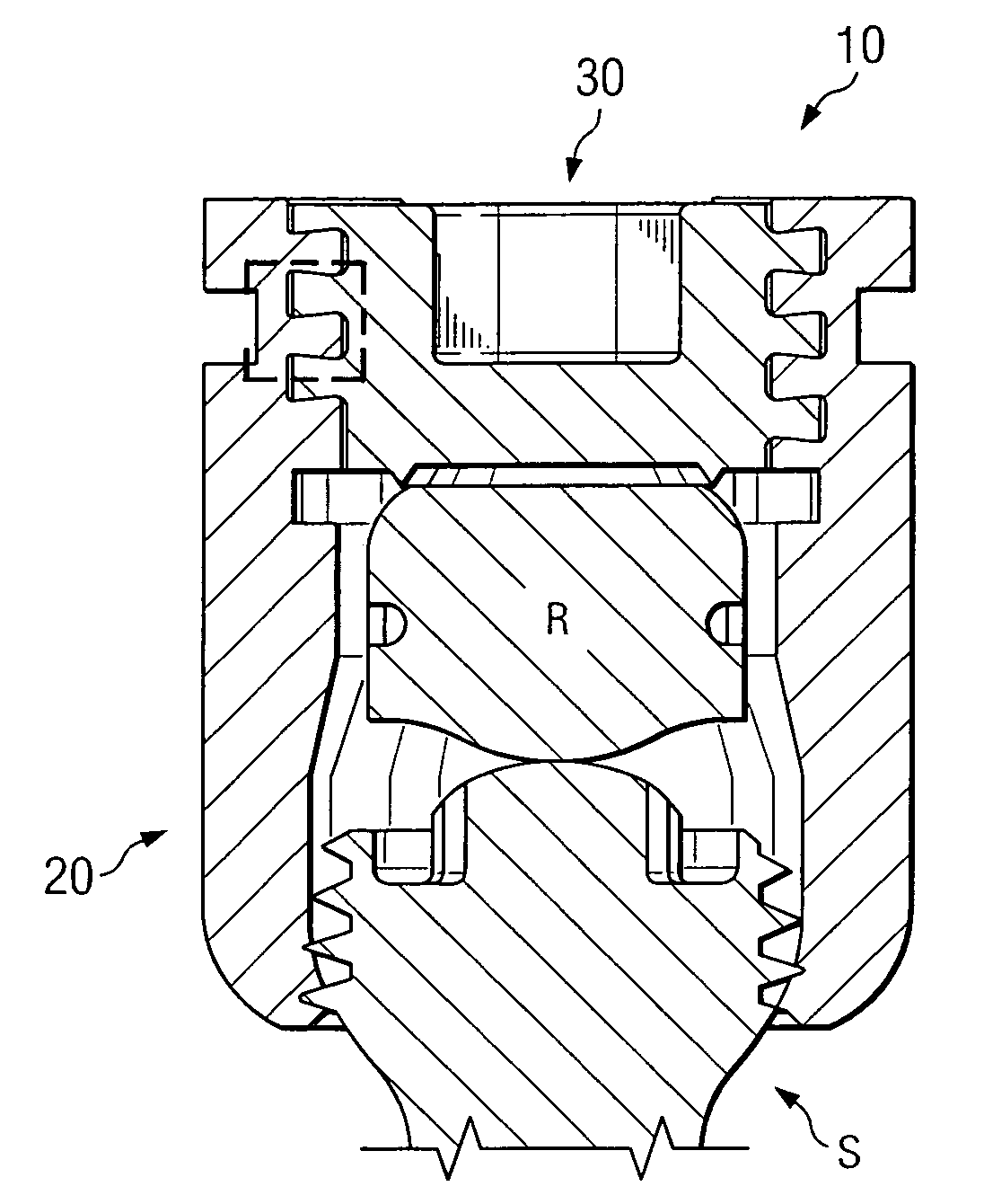
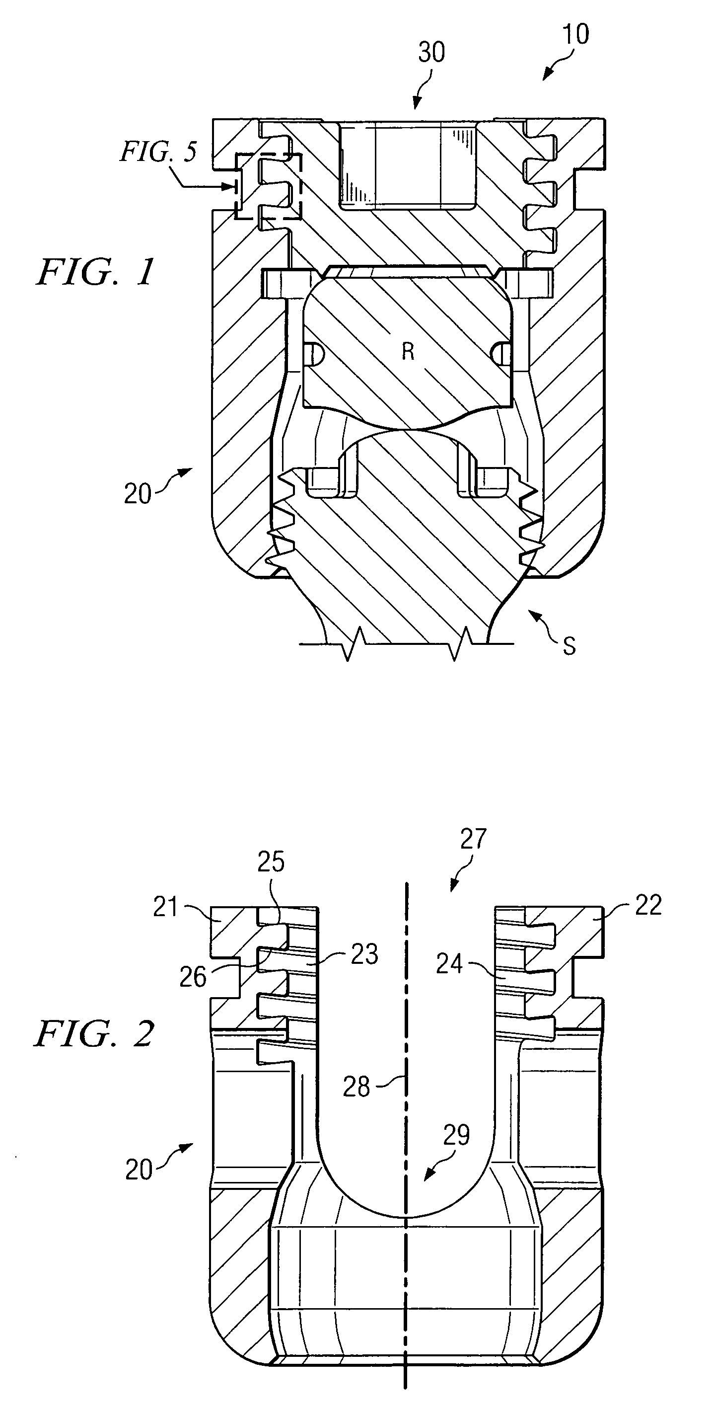
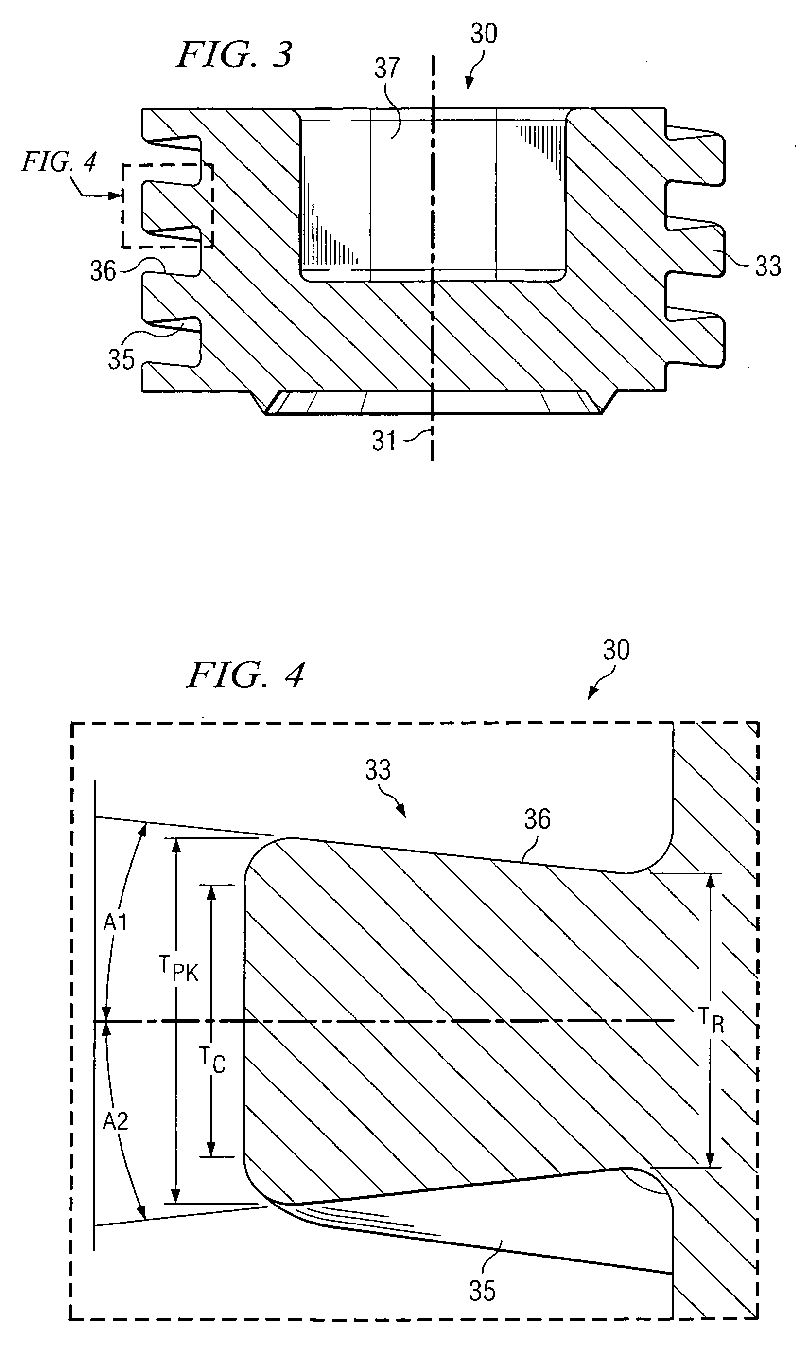
[0026] Various embodiments of the present invention are now described with reference to the above figures. As described further below, various embodiments are disclosed for a closure member and complementary receiving member that is particularly useful in medical implant devices. More particularly, in accordance with certain embodiments, a noncontiguous receiving member is included in a medical implant device. The noncontiguous receiving member includes a channel formed by a plurality of noncontiguous walls that include an inner (female) thread that forms a helical spiral about a center longitudinal axis of the channel. That is, the walls forming the channel have a noncontiguous diameter. Such receiving member, in certain implementations, is a cylindrical sleeve that has a longitudinal slit in one or more planes for at least part of its length. A closure member (e.g., set screw) has an outer (male) thread that is configured as a helical spiral about a center longitudinal axis of the...


PUM


Abstract

A closure member, such as a set screw, and complementary receiving member are included in a medical implant device. The receiving member has a plurality of noncontiguous, threaded walls substantially defining a bore for receiving the threaded closure member. When the closure member is inserted into the receiving member, their respective threads interlock to join the noncontiguous walls of the receiving member. The closure member has an outer thread configured to interlock with the inner walls of the receiving member in a manner that aids in preventing the noncontiguous walls of the receiving member from moving away from the closure member. In certain embodiments, the closure member's outer thread includes a trailing edge having a point that is rearward of the trailing edge's root, and the outer thread includes a leading edge having a point that is forward of the leading edge's root.

Description

TECHNICAL FIELD [0001] The present invention relates generally to the field of medical implant devices, and more particularly to medical implant devices which utilize a closure means for joining two components. More specifically, the invention relates to an apparatus which is particularly useful in closing a medical implant device and preventing splaying of parts of the medical implant device. Embodiments of the present invention provide a closure member, such as a set screw, that includes an external thread that is configured to aid in preventing noncontiguous walls of the structure within which the closure member is placed from moving away from the closure member. BACKGROUND OF THE INVENTION [0002] Set screws are used in many ways in order to lock one element of a device relative to another. Set screws are quite important in the art of medical implants, as it is often necessary to capture one element of the implant relative to another and to then lock the two relative to one anoth...

Claims


Application Information

Patent Timeline
29 Sep 2005
Publication
US20050216000A1
IPC
A61B17/70
CPC
A61B17/7005; A61B17/7037; A61B17/7032
Inventors
COLLERAN, DENNIS; SPITLER, JAMES