
Extraction screwdriver

a technology of extraction screw and removal tool, which is applied in the field of extraction screwdriver, can solve the problems of insufficient removal tool, inability to control the removal of screws, and insufficient removal tools to deal with the problem of fasteners, etc., and achieve the effect of increasing the engagement of the screw thread elemen

Inactive Publication Date: 2005-09-29
DEPUY SYNTHES PROD INC
View PDF99 Cites 75 Cited by
  • Summary
  • Abstract
  • Description
  • Claims
  • Application Information

AI Technical Summary

Benefits of technology

[0007] If a plate with through-holes or bores is being used, fasteners may be secured to the plate with individual locking clips to prevent the screws from backing out in situ. Each fastener may have, at its head, a circumferential groove which the locking clip of the plate can engage. The driver shaft may have a cruciform shape at its end similar to that of a Phillips screwdriver. The “fins” of the Phillips screwdriver may extend radially outward beyond the inner circumference of the groove in the screw head so as to expand the clip sufficiently to allow the screw to be removed from the plate and bone.
[0023] When the tool is engaged with the fastener and the tool is rotated to remove the fastener from the bone, the rotation may serve to increase engagement of the screw thread element with the fastener.

Problems solved by technology

Existing removal tools, however, are inadequate to deal with the problem of fasteners that are seated in substandard bone.
Such fasteners often may not be removed by simply backing out the screw, because the bone may not be strong enough to support the threads during the back out procedure.
Such arrangements, while allowing for removal of screws seated in substandard bone, do not allow for controlled removal of such screws, and instead rely on the surgeon to apply sufficient force to remove the screw but not so much force that the screw is ripped from the surrounding bone causing damage to the bone in which the screw is seated.
Risk of such damage may be great, due to a relatively high threshold force which maintains the bone screw in even substandard bone.

Method used


Image

  • Extraction screwdriver
  • Extraction screwdriver
  • Extraction screwdriver

Examples


Embodiment Construction

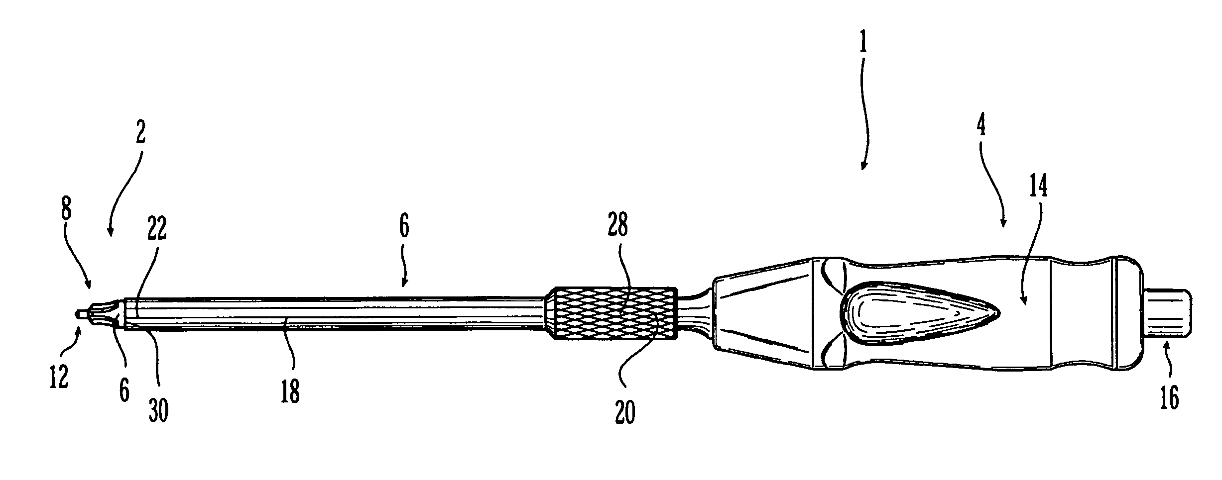
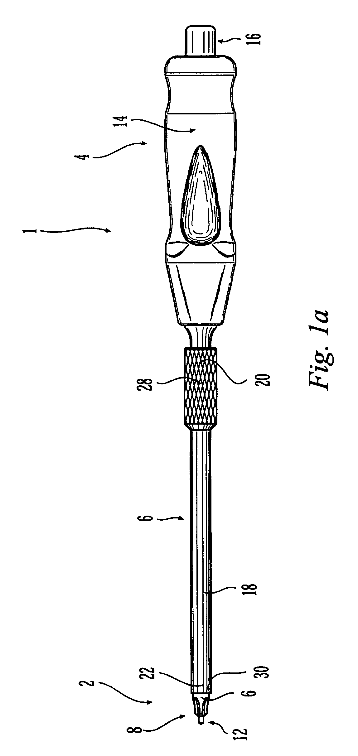
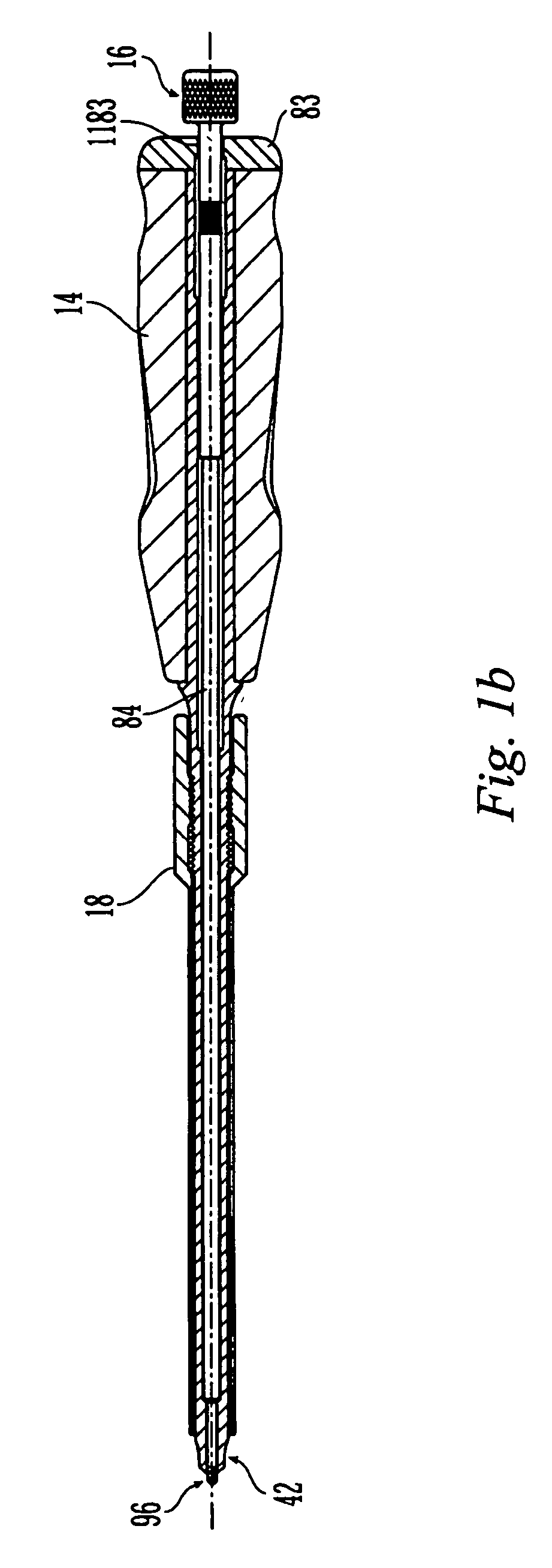
[0039] A first embodiment of the fastener driving and removal tool (“the tool”) is shown in FIGS. 1a and 1b. The tool 1 may take the general shape and appearance of a traditional screw driving device, with a distal fastener engaging end 2 and a proximal user end 4, the two ends connected by a drive shaft 6. The fastener engaging end 2 may have a first fastener engaging surface 8 configured and dimensioned to rotationally engage the head of a fastener 32, such as a bone screw (FIG. 2). The fastener engaging end 2 may also have a second fastener engaging surface 12 configured and dimensioned to retain the fastener 32 in fixed axial relation with the tool 1. The user end 4 may comprise a handle 14 configured and dimensioned for gripping by a user. The user end 4 may further comprise an actuator 16 in communication with the second fastener engaging surface 12, thus allowing the user to axially engage the fastener 32 with the tool 1 by actuating the actuator 16. The tool 1 may further co...


PUM


Abstract

The present invention provides a simplified bone fastener removal tool which allows the surgeon to remove bone screws or other bone fasteners from bone, and from bone plates incorporating fastener locking elements. The tool includes an inner shaft which axially engages the bone fastener, a drive shaft which allows the fastener to be rotated using the tool, and an internally threaded outer sleeve which, in combination with the drive shaft, allows for a controlled removal of the fastener from the bone plate and bone. In particular, the internal threads of the outer sleeve engage external threads on the drive shaft, such that rotating the drive shaft while maintaining the outer sleeve fixed causes the drive shaft to translate with respect to the sleeve. Thus, when a fastener is axially engaged with the drive shaft, a controlled removal of the fastener from the bone and bone plate is accomplished simply by rotating the drive shaft with respect to the outer sleeve. No pulling on the fastener is necessary. A method of using the tool is also provided.

Description

FIELD OF THE INVENTION [0001] The invention is related to a fastener driving and removal tool. More particularly, the invention relates to an improved fastener driving and removal tool for driving and extracting screws used to secure an orthopedic bone plate to bone. BACKGROUND OF THE INVENTION [0002] Orthopedic fixation devices such as plates are frequently coupled to bone with fasteners inserted through plate holes. It is known that such fasteners can often be removed with typical screwdrivers and variations of typical screwdrivers. It is also known that securing such fasteners to the bone plate, for example through the use of expanding locking rings, can decrease the incidence of premature screw loosening and back out. It is also known that, to remove such locked fasteners, removal tools having mechanisms to expand locking rings can be used. [0003] Existing removal tools, however, are inadequate to deal with the problem of fasteners that are seated in substandard bone. Such faste...

Claims


Application Information

Patent Timeline
Patent Type & Authority Applications(United States)
IPC IPC(8): A61B17/56A61B17/80A61B17/86A61B17/88A61B17/92
CPCA61B17/8047A61B17/92A61B17/8888A61B17/861A61B17/56A61B17/88
Inventor SUH, SEAN S.RATHBUN, DAVID SAWYER
Owner DEPUY SYNTHES PROD INC
Features
  • Generate Ideas
  • Intellectual Property
  • Life Sciences
  • Materials
  • Tech Scout
  • Unparalleled Data Quality
  • Higher Quality Content
  • 60% Fewer Hallucinations
Learn More