

Wiper blade connecting structure
- Summary
- Abstract
- Description
- Claims
- Application Information
AI Technical Summary
Benefits of technology
Problems solved by technology
Method used
Image

Examples
Embodiment Construction
[0027] Hereinafter, embodiments according to the present invention will be explained with reference to the drawings.
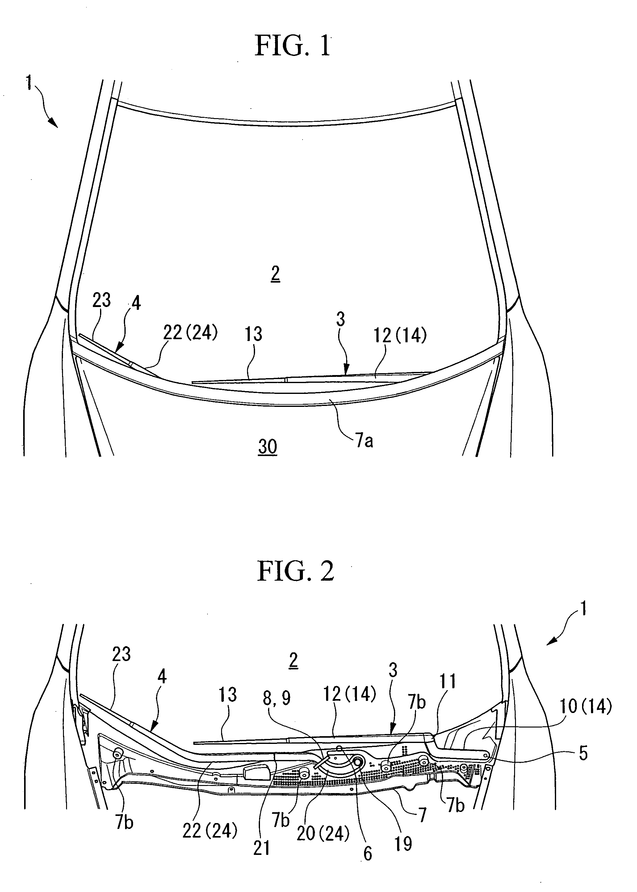
[0028]FIG. 1 is a perspective view of a front portion of a vehicle, to which an wiper apparatus is attached, in an embodiment of the present invention. FIG. 2 is a perspective view omitting the hood and the upper cowl top garnish in FIG. 1.
[0029] As shown in FIGS. 1 and 2, in a vehicle 1, a pair of wiper apparatuses 3 and 4 is provided so as to wipe a windshield 2. The wiper apparatuses 3 and 4 are respectively linked with pivots 5 and 6 which are rotated by driving devices (not shown).
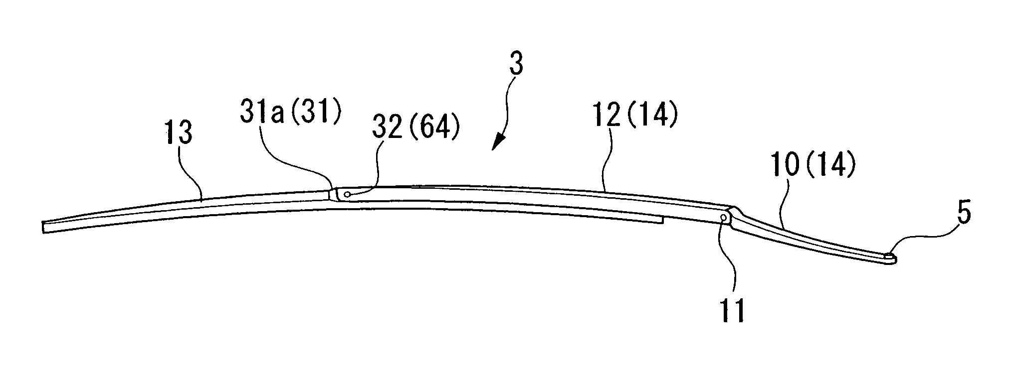
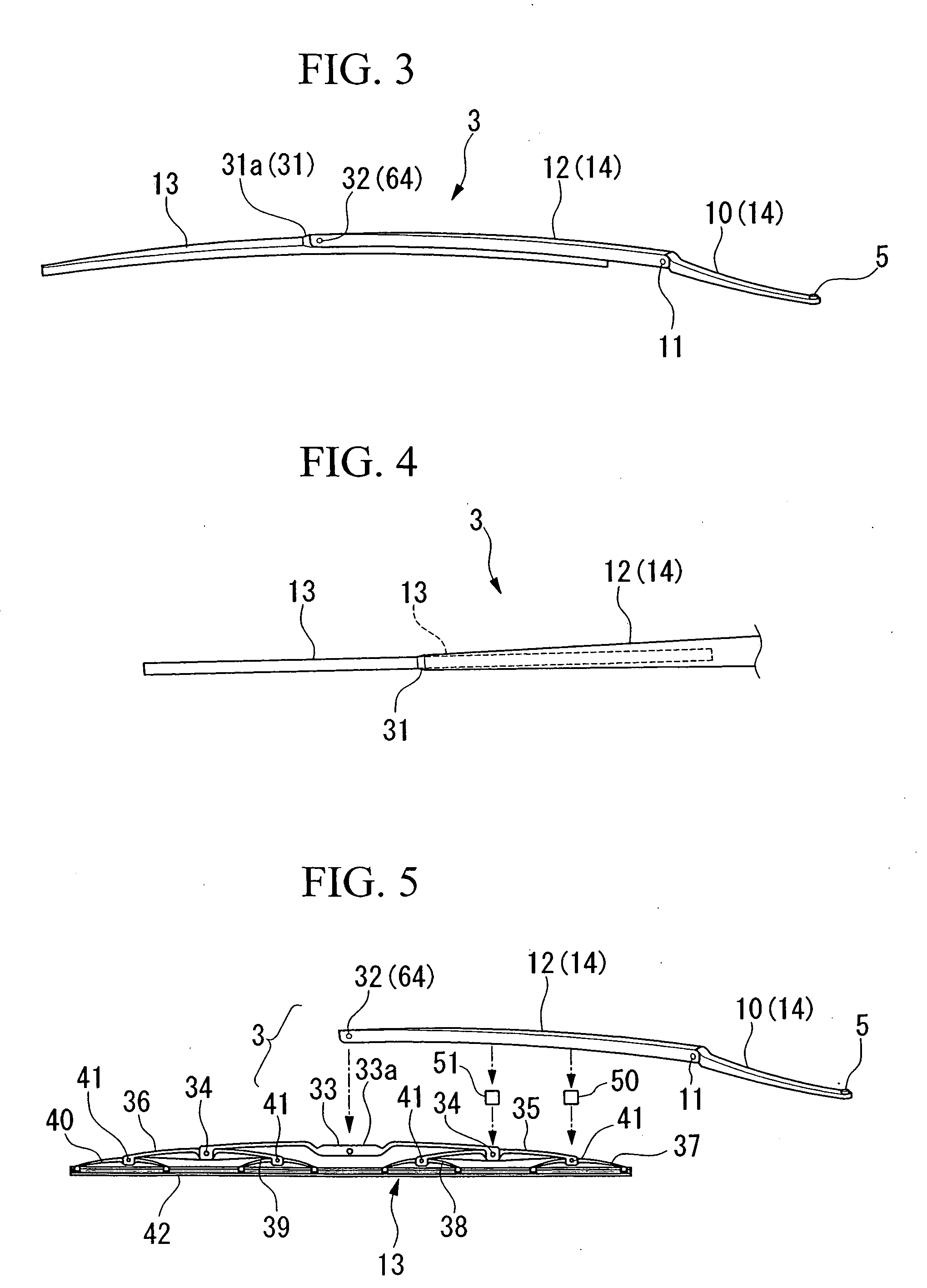
[0030] The first wiper apparatus 3 is provided at the vehicle body's left side, and the pivot 5 of the wiper apparatus 3, positioned at the end proximate to the vehicle body's left side as shown in FIG. 2, protrudes from a cowl top garnish 7 which is arranged at the lower side of the windshield 2 and oriented in the width direction of the vehicle. An arm base 10 is attached to the piv...
PUM
 Abstract
Description
Claims
Application Information