Rolling die

a die and rolling technology, applied in the field of rolling dies, can solve the problems of cracking or localized damage, shortening the life of the die,

Inactive Publication Date: 2005-10-06
SANMEI SEISAKUSHO
View PDF6 Cites 10 Cited by
  • Summary
  • Abstract
  • Description
  • Claims
  • Application Information

AI Technical Summary

Problems solved by technology

However, since the cross-sectional shape of the processing teeth of the rolling dies is the same through a bite portion, a finishing portion, and a roll-off portion, cracking or localized damage occurs easily near the tooth tip of the bite starting point where a hardened workpiece is initially processed, and the product life of the die is shortened.
Because the teeth in the bite potion sharply cut into the raw material, however, there have been problems of cracking or localized damage when rolling a workpiece of a hardened raw material.

Method used


Image

  • Rolling die
  • Rolling die
  • Rolling die

Examples


Embodiment Construction

[0028] Reference will now be made in detail to exemplary embodiments of the invention, examples of which are illustrated in the accompanying drawings. Wherever possible, the same reference numbers will be used throughout the drawings to refer to the same or like parts.

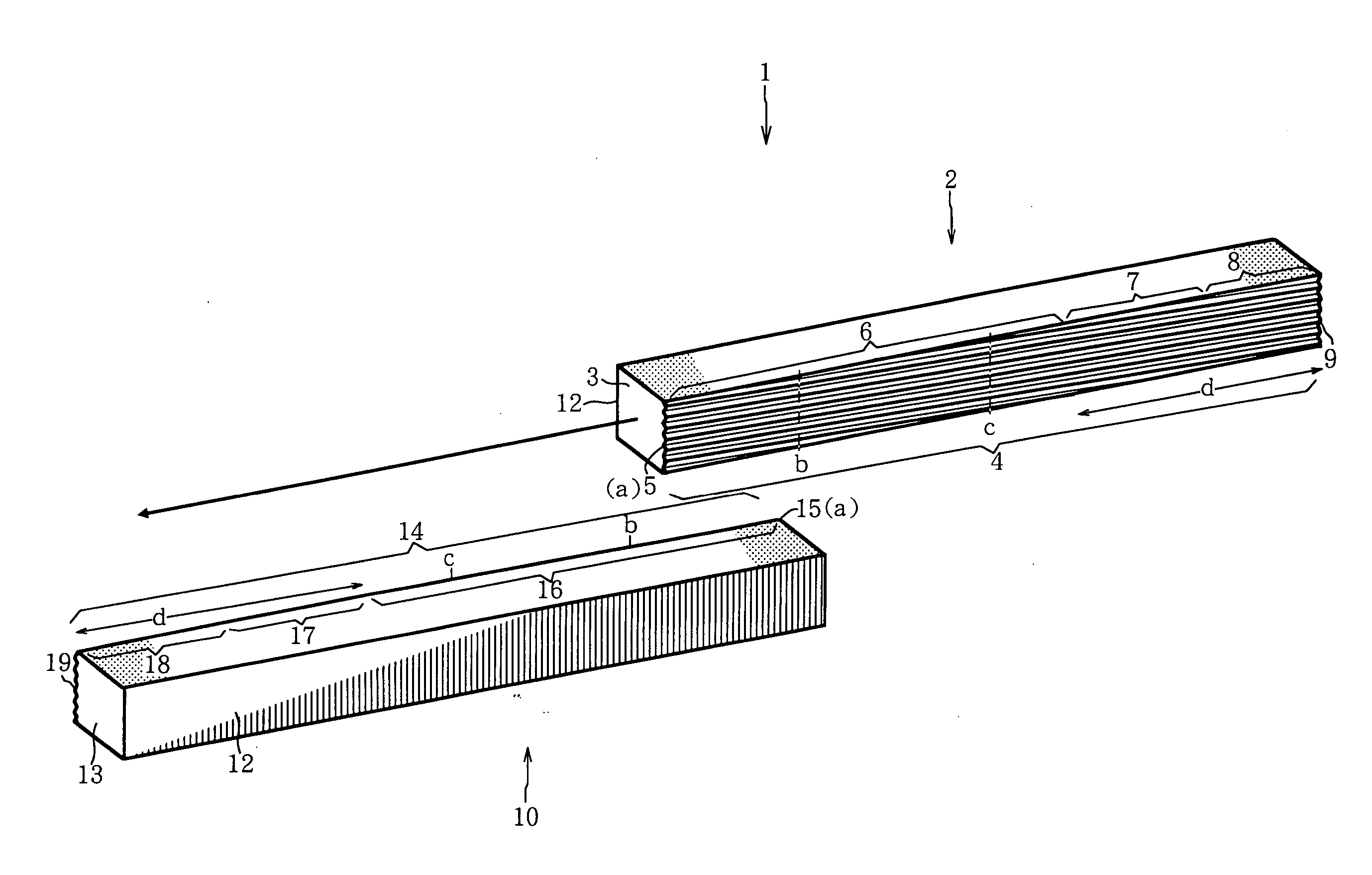
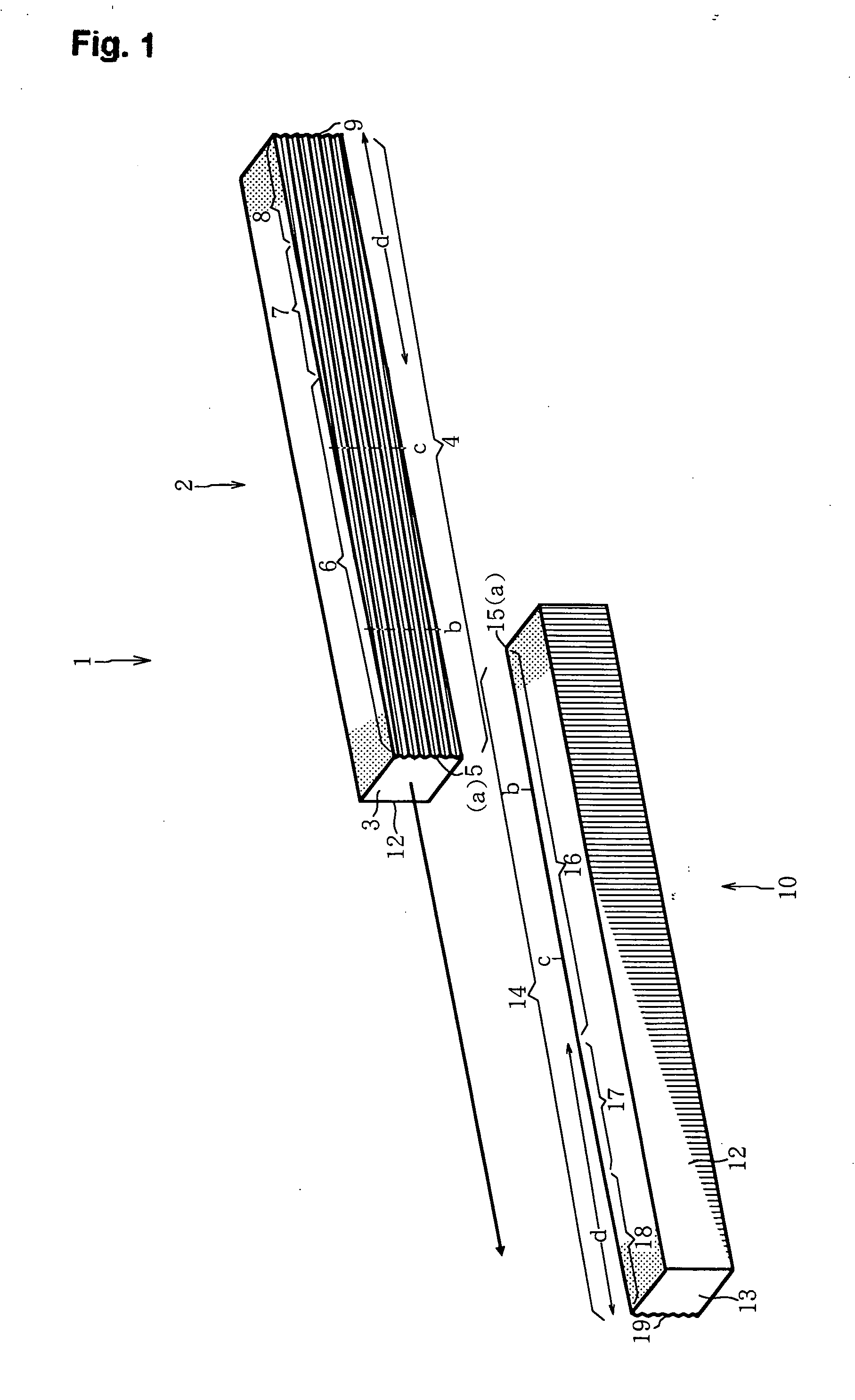
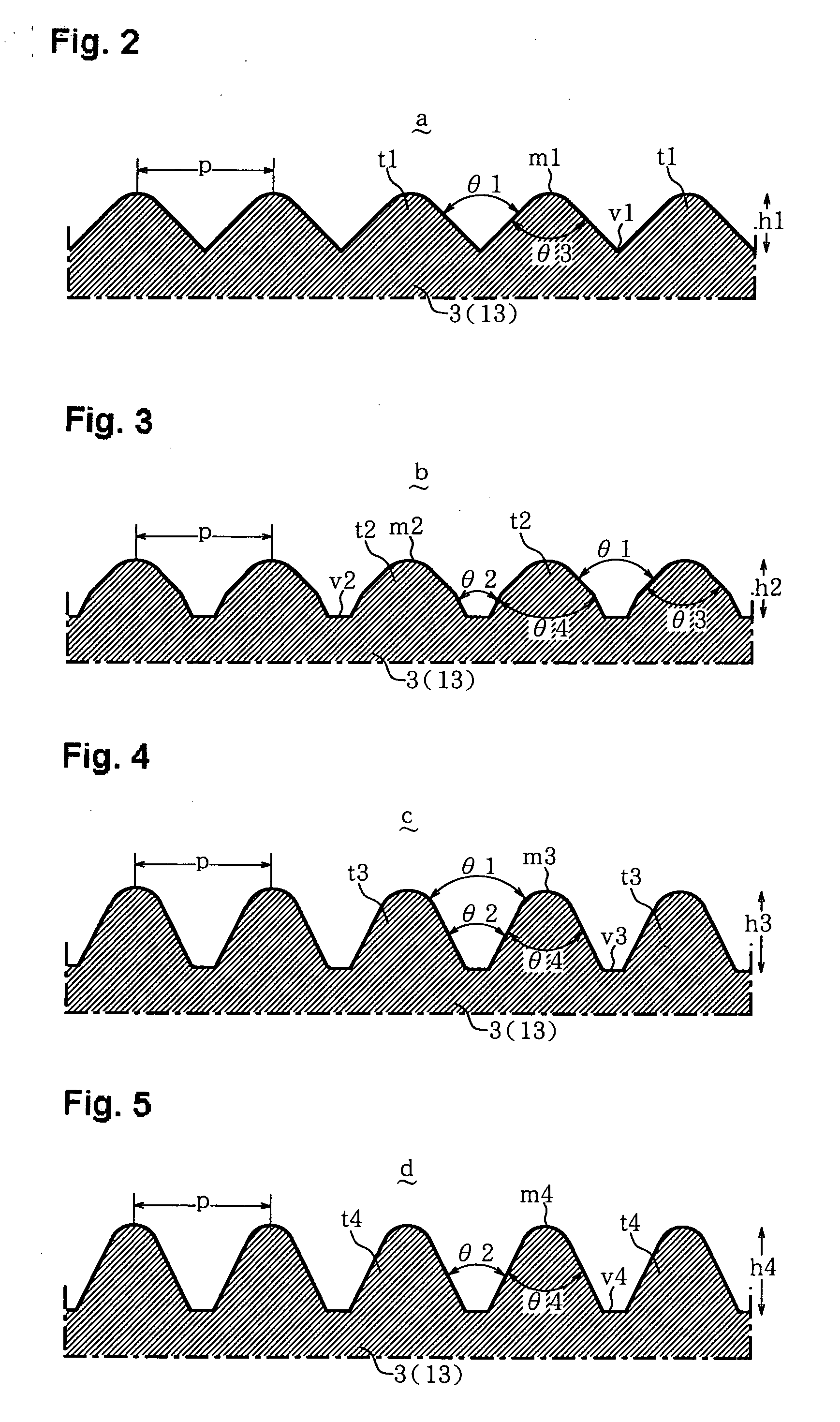
[0029] A rolling die according to one embodiment of the invention includes a bite portion having bite processing teeth and a finishing portion having finishing processing teeth. The bite portion includes bite processing teeth at a bite starting point for a workpiece. The processing teeth at the starting point in the bite portion have a lower tooth height than the processing teeth in the finishing portion, and the bite processing teeth at the starting point in the bite portion have a larger tooth tip angle and a larger trough angle than the finishing processing teeth in the finishing portion.

[0030] In this regard, since the processing teeth of the bite starting point are shallow and have an obtuse angle for the initia...


PUM

PropertyMeasurementUnit
trough angleaaaaaaaaaa
Lengthaaaaaaaaaa

Abstract

A rolling die is provided. The rolling die includes a bite portion having bite processing teeth at a bite starting point for a workpiece, and a finishing portion having finishing processing teeth. The bite processing teeth at the starting point in the bite portion have lower tooth height than the finishing processing teeth in the finishing portion. The bite processing teeth have a larger tooth tip angle and a larger trough angle than the finishing processing teeth.

Description

CROSS REFERENCE TO RELATED APPLICATION [0001] This application is based upon and claims the benefit of priority from Japanese Patent Application No. 2004-103839, filed on Mar. 31, 2004, the entire content of which is incorporated herein by reference. FIELD OF THE INVENTION [0002] The present invention relates to a rolling die for rolling bolts or screws. More particularly, the invention relates to a rolling die having stabilized formation precision and high durability. BACKGROUND [0003] Fasteners, such as bolts or screws, continuously form screw crests and troughs on the peripheral surface with each single rotation by holding a rod-like workpiece between a pair of flat die pieces provided with moderately inclined processing teeth on one side surface, and relatively moving one flat die with respect to the other side surface. Typically, the processing teeth have the same cross-sectional shape, extending from a bite portion that includes a starting point on one surface side to a roll-o...

Claims


Application Information

Patent Timeline
Patent Type & Authority Applications(United States)
IPC IPC(8): B21H3/02B21H3/04B21H3/06
CPCB21H3/06B21H3/02
Inventor TANIGUCHI, NAOSHIGENONAKA, YOSHIOHAYASHI, NORISHIGEMASUO, KAZUHIKO
Owner SANMEI SEISAKUSHO
Why Eureka
Try Eureka