Gear with large tooth lead modification quantity and processing method thereof

A technology of modification amount and tooth direction, which is applied in the direction of belt/chain/gear, components with teeth, portable lifting device, etc. It can solve the problem of increased grinding amount of tooth surface, insufficient tooth surface layer depth of grinding boss, Reduce gear strength and service life

Active Publication Date: 2015-05-27
CRRC QISHUYAN INSTITUTE CO LTD
View PDF5 Cites 8 Cited by
  • Summary
  • Abstract
  • Description
  • Claims
  • Application Information

AI Technical Summary

Problems solved by technology

[0002] The traction gears of railway locomotives and engineering machinery often use active gears for cantilever-mounted meshing transmission. This structure is simple and reliable. It is bound to increase the amount of gear modification
The traditional design and processing method is to first design the basic tooth surface with constant displacement coefficient and common normal line, and then carry out the design of the tooth profile modification. The basic tooth su

Method used


Image

  • Gear with large tooth lead modification quantity and processing method thereof
  • Gear with large tooth lead modification quantity and processing method thereof
  • Gear with large tooth lead modification quantity and processing method thereof

Examples


Embodiment Construction

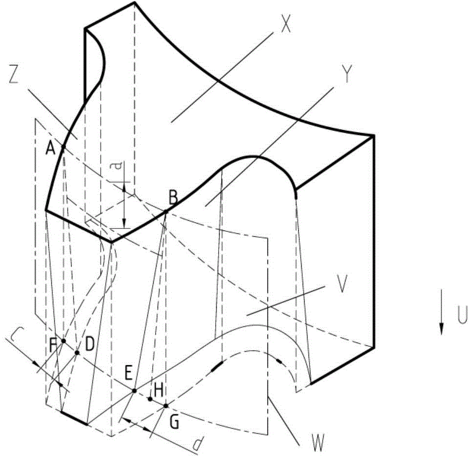
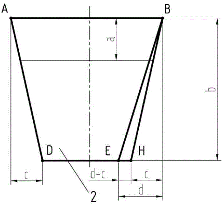
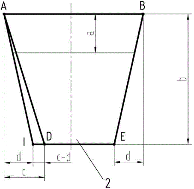
[0049] like figure 1 , 2 , 3, 4, and 5, a gear with a large tooth direction modification amount of the present invention has a tooth number of z, a modulus of m, a tooth width of b, and a pressure angle of α. The large tooth direction modification amount gear 2. The displacement coefficient of the upper end face tooth profile is x, the common normal line of the upper end face tooth profile of the large tooth direction modification gear 2 is W, and the public normal line of the upper end face tooth profile of the large tooth direction modification amount gear 2 W is determined according to the following formulas I and II:

[0050] W=mcosα·[π(k-0.5)+z·invα]+2xmsinα (I),

[0051]

[0052] In formula II, the value of k is rounded to an integer;

[0053] The displacement coefficient of the cross-sectional tooth profile at the distance a from the upper end surface of the gear 2 with large tooth direction modification amount is x a , The public normal line of the cross-section...


PUM


Abstract

The invention discloses a gear with large tooth lead modification quantity and a processing method thereof. the modification coefficient of a tooth shape of the upper end face of the gear with large tooth lead modification quantity is x, and the common normal line of the tooth shape of the upper end face is W; the modification coefficient of the tooth shape of the section at a position, spaced from the upper end face by a, on the gear with the large tooth lead modification quantity is xa, and the common normal line of the tooth shape of the section at the position, spaced from the upper end face by a, on the gear with the large tooth lead modification quantity is Wa; the intersecting line of the left tooth surface and the cylindrical surface of the reference circle is a molded line AD, and the intersecting line of the right tooth surface and the cylindrical surface of the reference circle is a molded line BE; an intersection between the molded line AD and the upper end face X is a point A, and an intersection between the molded line AD and the lower end face V is a point D; an intersection between the molded line BE and the upper end face X is a point B, and an intersection between the molded line BE and the lower end face V is a point E; a point F is a projection of the point A on the lower end face V in the axial direction U; a point G is a projection of the point B on the lower end face V in the axial direction U. The processing method comprises a step of 1, performing hobbing processing on a gear blank, and further comprises a second step and a third step. According to the processing method, the tooth direction grinding modification quantity can be reduced, and the defects, such as reduction of the hardness of the tooth surface, caused by a large tooth grinding amount are avoided.

Description

technical field [0001] The invention relates to a gear and a processing method thereof, and is especially suitable for a cantilever-mounted involute cylindrical gear with a hard tooth surface and a large tooth direction modification amount with a large tooth surface meshing misalignment. Background technique [0002] The traction gears of railway locomotives and construction machinery often use active gear cantilever-installed meshing transmissions. This structure is simple and reliable. It is bound to increase the modification amount of the gear. The traditional design and processing method is to first design the basic tooth surface with constant displacement coefficient and common normal, and then carry out the design of the tooth profile modification. The basic tooth surface is realized by hobbing during processing, and the tooth profile modification is realized by grinding after heat treatment. The excessive amount of modification increases the grinding amount of the to...

Claims


Application Information

Patent Timeline
IPC IPC(8): F16H55/17B23P15/14
CPCB23P15/14F16H55/08F16H55/17
Inventor 颜力刘忠伟文超
Owner CRRC QISHUYAN INSTITUTE CO LTD
Why Eureka
Try Eureka