
Broad-Pole Type Square-Wave Three-Phase Brushless Permanent Magnet Direct Current Motor and Assembling Method Thereof

a permanent magnet, three-phase brushless technology, applied in the direction of dynamo-electric machines, electrical apparatus, magnetic circuit shapes/forms/construction, etc., can solve the problems of large fluctuation of switching torque of wave permanent magnet motor, complex control system, and no desired effect of these measures in applications, etc., to minimize the positioning torque as required, reduce manufacturing costs, and simplify the effect of structur

Active Publication Date: 2013-05-02
SHENZHEN TATFOOK POWER EQUIP CO LTD
View PDF2 Cites 9 Cited by
  • Summary
  • Abstract
  • Description
  • Claims
  • Application Information

AI Technical Summary

Benefits of technology

The present invention proposes a new type of square-wave permanent magnet motor that overcomes the performance and cost issues of conventional motors. The motor has a unique structure with a number of poles that generates a flat air-gap magnetic field. It has a simplified structure and low manufacture cost, with a simplified structure and low manufacture cost. The motor produces a force that is 33% greater than conventional motors with conventionally distributed windings, while consuming much less copper. It is stable and smooth with a fluctuation index equal to that of conventional motors with conventionally distributed windings. The motor generates a stable and smooth moment when driven by three-phase square-wave current.

Problems solved by technology

However, the biggest drawback of the square-wave permanent magnet motor is its relatively large switching torque fluctuation.
Researchers have proposed many compensation measures, trying to overcome this drawback, but none of these measures has gained desired effects in applications.
Nevertheless, accompanied by the use of the sine-wave permanent magnet motor is a much more complicated control system and a rapidly increased manufacture cost.
Due to the aforesaid deficiency, it is restricted to applications that do not have high requirements.
Objectively speaking, this motor still suffers from a great iron loss in high speed applications.

Method used


Image

  • Broad-Pole Type Square-Wave Three-Phase Brushless Permanent Magnet Direct Current Motor and Assembling Method Thereof
  • Broad-Pole Type Square-Wave Three-Phase Brushless Permanent Magnet Direct Current Motor and Assembling Method Thereof
  • Broad-Pole Type Square-Wave Three-Phase Brushless Permanent Magnet Direct Current Motor and Assembling Method Thereof

Examples


Embodiment Construction

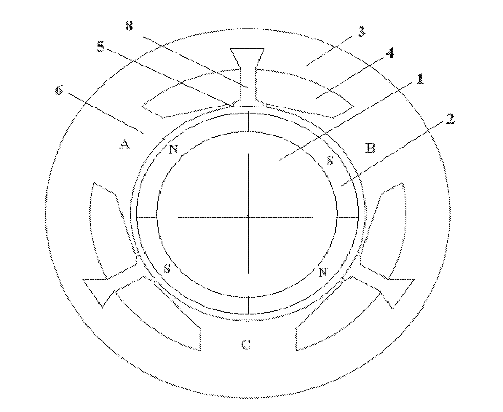
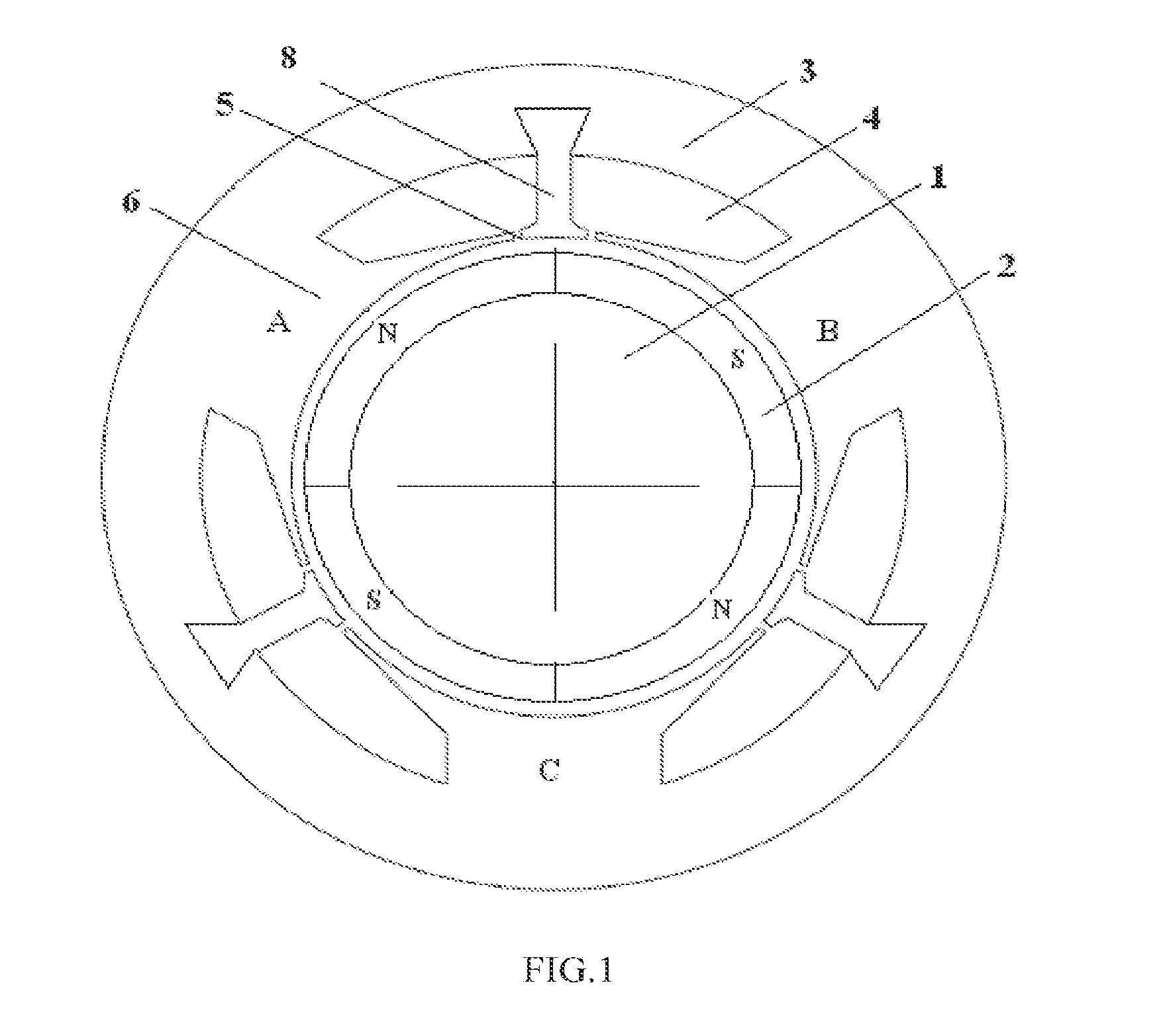
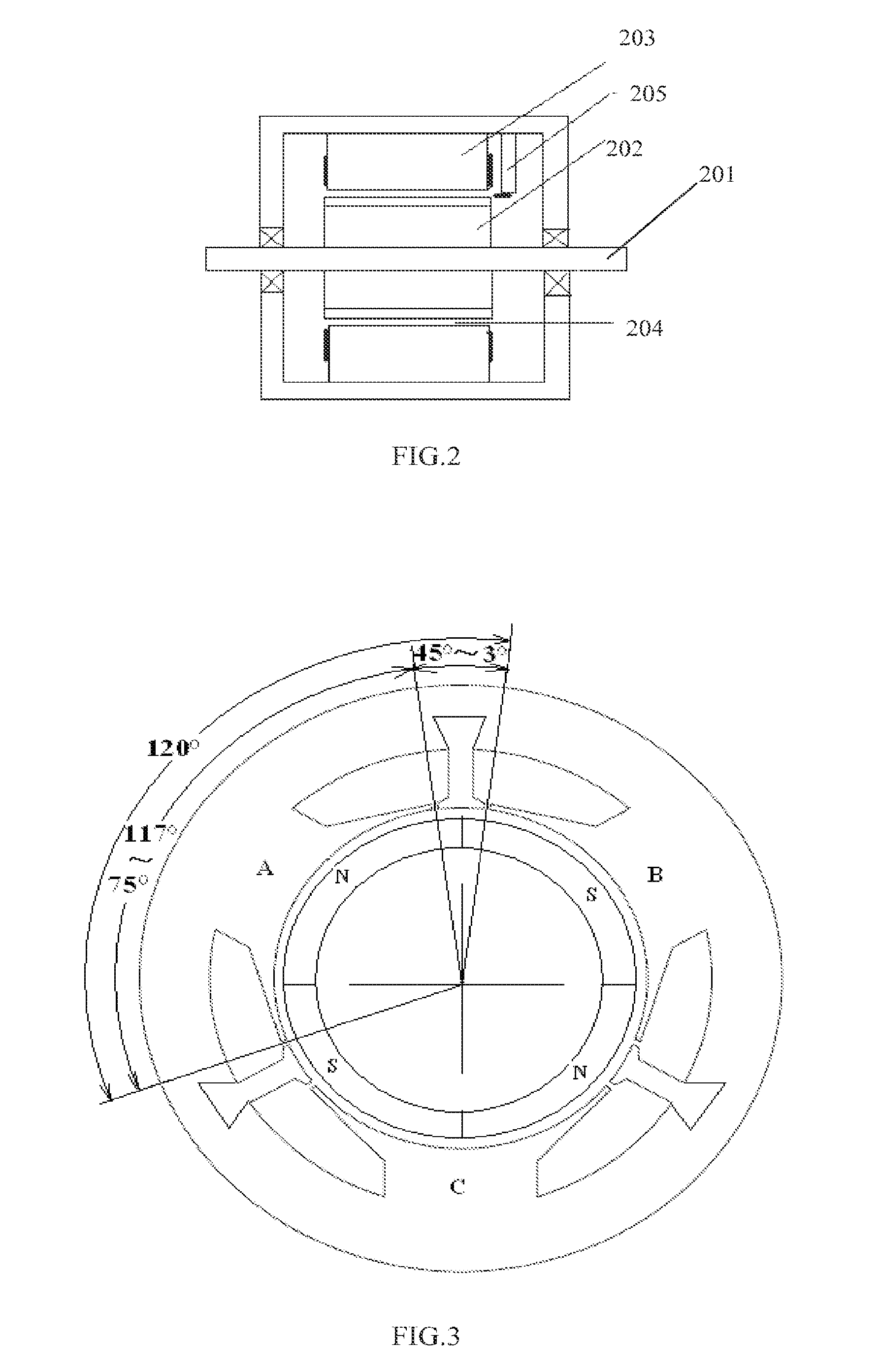
[0028]One of the preferred embodiments of the present invention is show in FIG. 1 through FIG. 7. FIG. 2 illustrates an overall structure of the brushless permanent magnet direct current motor, which mainly comprises a rotary axis 201, a rotor 202, and a stator 203 etc., wherein a physical air gap 204 having a width between 0.2 mm and 3 mm is formed between the rotor 202 and the stator 203. A Hall position sensor is used to detect the rotor position. The Hall position sensor is established on the stator holder 205, the magnet-sensitive direction of the Hall position sensor being identical to the normal line direction of the rotor, and an air gap between 1 mm and 3 mm being formed between the Hall position sensor and the outer circle of the magnet steel of the rotor (i.e., the permanent magnets).

[0029]It can be seen from FIG. 1 that around the rotor core 1 is established two pairs of permanent magnets (totaling four permanent magnets), the two N poles and two S poles alternating. Tha...


PUM


Abstract

A broad-pole type square-wave three-phase brushless permanent magnet direct current motor and an assembling method thereof are disclosed. The number of magnetic poles on a rotor core is: 2P=4. The number of slots in a stator core is: Z=6. Six teeth on the stator are composed of three large teeth and three small teeth. The sum of mechanical angles of one large tooth and one small tooth is 120 degree. Electrical angles corresponding to the mechanical angles are: P*120=240°. Three-phase concentrated windings are wound on three large teeth separately, and only one winding is arranged at each phase. The advantages of the motor are low positioning torque, simple structure, effective production cost, convenient to wind the windings, and low copper loss, etc.

Description

TECHNICAL FIELD[0001]The present invention relates to a permanent magnet direct current motor, and more particularly to a broad-pole type square-wave three-phase brushless permanent magnet direct current motor and an assembling method thereof. The motor as provided is adapted for direct drive and position and rate servo control applications.BACKGROUND TECHNOLOGY[0002]According to drive current and back EMF waveform, a permanent magnet motor may be classified into a sine-wave permanent magnet motor and a square-wave permanent magnet motor. Generally, the sine-wave permanent magnet motor is referred to as a permanent magnet synchronous motor (PMSM) or a sine-wave AC servo motor, while the square-wave permanent magnet motor is referred to as a square-wave brushless DC motor (BLDCM).[0003]The square-wave permanent magnet motor was widely used in 1980s. It has almost the same external characteristics as a brush DC motor and can be controlled in a simple mode. However, the biggest drawbac...

Claims


Application Information

Patent Timeline
Patent Type & Authority Applications(United States)
IPC IPC(8): H02K1/14H02K11/00
CPCH02K1/146H02K2213/03H02K21/16H02K11/0021
Inventor QI, YAMEILI, TIECAIZHOU, ZHAOYONGLAN, WEILONGLIAO, ZHIHUILI, SHINIAN
Owner SHENZHEN TATFOOK POWER EQUIP CO LTD
Learn More