
Device for automatic tire inflation and tire pressure display

a technology of automatic tire inflation and display device, which is applied in vehicle tyre testing, instruments, roads, etc., can solve the problems of increasing abrasion, promoting flat tires, and tire loss of resiliency,

Inactive Publication Date: 2005-10-06
PARTNER TECH
View PDF7 Cites 3 Cited by
  • Summary
  • Abstract
  • Description
  • Claims
  • Application Information

AI Technical Summary

Benefits of technology

[0006] One object of the present invention is to provide a tire pressure measurement device capable of wirelessly detecting the tire temperature and tire balance.
[0007] To achieve the above object, the present invention proposes a device for automatic tire inflation and tire pressure display. The device comprises a tire pressure measurement unit, a tire temperature sensor and a gradienter. The tire pressure measurement unit detects the tire pressure value of a tested tire and wirelessly displays it on a display unit in a vehicle. A user can then maneuver a function key to select an operation according to data displayed on the display unit and send this message to a tire room for carrying out inflation/deflation of the tire. The tire temperature sensor is disposed in the tire room and used to measure the temperature of the tire for wireless display on the display unit in the vehicle via the tire pressure measurement unit so that the user can know the present status. The gradient

Problems solved by technology

If the pneumatic level is insufficient, the load of the tire will be too large, the tire body has to bear the load, causing deformation of the tire body and increased contact area with the ground This results in increased abrasion and promotes flat tires.
If the pneumatic level is too high, the tire will lose its resiliency and absorb shock poorly.
The internal structure of the tire will bear a too large tension and be easily damaged.
If the steering tire is imbalanced, the vibration will be violent and cause damage to the steering mechanism or even result in a serious accident when driving at a high speed.
If the weight of the tire is nonuniform, the centrifugal force due to rotation will be nonuniform, hence causing vibration.
If the rotation speed is high, this vibration will be large enough to damage each component of the tire and the suspension system.
Moreover, if the tire temperature is too high, the load of the tire will be too large, to cause hazards like a flat tire.

Method used


Image

  • Device for automatic tire inflation and tire pressure display
  • Device for automatic tire inflation and tire pressure display
  • Device for automatic tire inflation and tire pressure display

Examples


Embodiment Construction

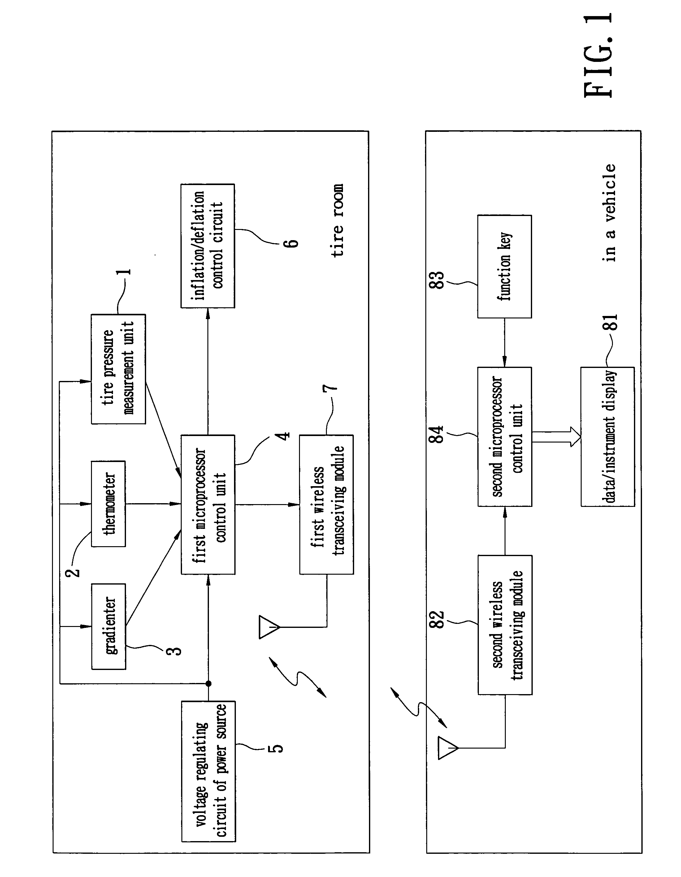
[0012] As shown in FIG. 1, a device for automatic tire inflation and tire pressure display of the present invention comprises a tire pressure measurement unit 1, a thermometer 2, a gradienter 3, a first microprocessor control unit 4, a voltage regulating circuit of power source 5, an inflation / deflation control component 6 and a first wireless transceiving module 7.

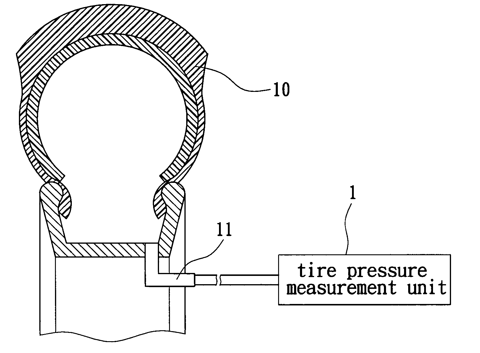
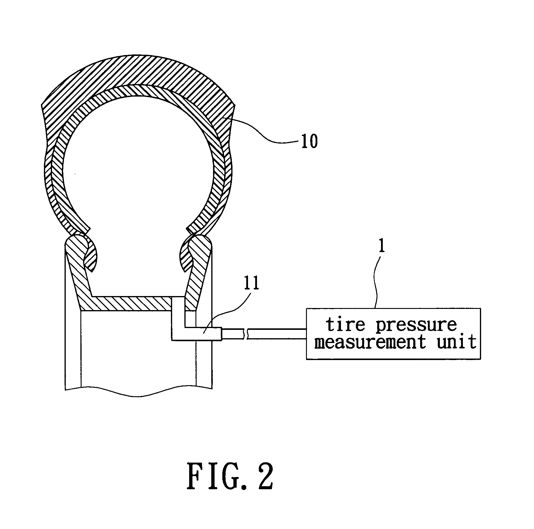
[0013] As shown in FIG. 2, the tire pressure measurement unit 1 is fixedly arranged on an air cock 11 of a tire 10, and is used to detect the tire pressure value of a tested tire to measure abnormal signals such as high tire pressure, low tire pressure or an insufficient electric power.

[0014] The thermometer 2 is disposed in a tire room for measuring the temperature of the tire.

[0015] The gradienter 3 is disposed in the tire room for measuring the balance state of the tire.

[0016] The voltage regulating circuit of power source 5 is used to provide working voltages for subassemblies.

[0017] The first microprocessor cont...


PUM


Abstract

A device for automatic tire inflation and tire pressure display has a tire pressure measurement unit, a tire temperature sensor (a thermometer) and a gradienter for measuring the tire balance. The tire pressure measurement unit has a tire pressure measurement unit, a voltage regulating circuit of power source, a microprocessor control unit, a wireless transceiving module and an inflation / deflation control component. The tire pressure measurement unit measures the tire pressure value of a tested tire. The tire pressure value is then wirelessly displayed on a display unit in a vehicle so that the user can know the present status of a tire. The user can also maneuver a function key to select an operation according to the displayed data and send this message to the tire room to execute inflation or deflation of the tire.

Description

FIELD OF THE INVENTION [0001] The present invention relates to a device for automatic tire inflation and tire pressure display and, more particularly, to a tire pressure measurement device capable of wirelessly detecting tire temperature and tire balance. BACKGROUND OF THE INVENTION [0002] Tire load has a direct relation with pneumatic pressure. Most of the tire load is born by compressed air. If the pneumatic level is insufficient, the load of the tire will be too large, the tire body has to bear the load, causing deformation of the tire body and increased contact area with the ground This results in increased abrasion and promotes flat tires. If the pneumatic level is too high, the tire will lose its resiliency and absorb shock poorly. The internal structure of the tire will bear a too large tension and be easily damaged. The tire will be too circular and only the center of the tire face can touch the ground to speed up abrasion of the tire. [0003] Additionally, whether the rotati...

Claims


Application Information

Patent Timeline
IPC IPC(8): B60C23/00B60C23/04B60C23/10G01L17/00G01M17/02
CPCB60C23/001G01L17/00B60C23/0408Y10T137/36
Inventor YUEH, WEN HSIANG
Owner PARTNER TECH
Learn More