Heat exchanger and associated method

a technology of heat exchanger and heat exchanger, which is applied in the direction of lighting and heating apparatus, tubular elements, and stationary conduit assemblies, etc., can solve the problems of high temperature process that requires expensive brazing equipment and complex process control, and still a relatively expensive and heavy oil cooler

Inactive Publication Date: 2005-10-06
EDC AUTOMOTIVE
View PDF10 Cites 11 Cited by
  • Summary
  • Abstract
  • Description
  • Claims
  • Application Information

AI Technical Summary

Problems solved by technology

This type of oil cooler, which consists of concentric brass tubes between which the oil flows, is typically made by brazing, a high temperature process that requires expensive brazing equipment and complex process control.
The result is a relatively expensive and heavy oil cooler. FIG. 2A shows the cross section of the oil cooler.
The u

Method used


Image

  • Heat exchanger and associated method
  • Heat exchanger and associated method
  • Heat exchanger and associated method

Examples


Embodiment Construction

[0042] The following description of various aspects of the invention is merely exemplary in nature and is in no way intended to limit the invention, its application, or uses. The present teachings are applicable, but are not limited to, the area of cooling of transmission oil and / or engine oil in automotive applications. The present teachings are, for example, also applicable to diverse areas such as railways, ships, aircraft, machine tool, power generation equipment and others.

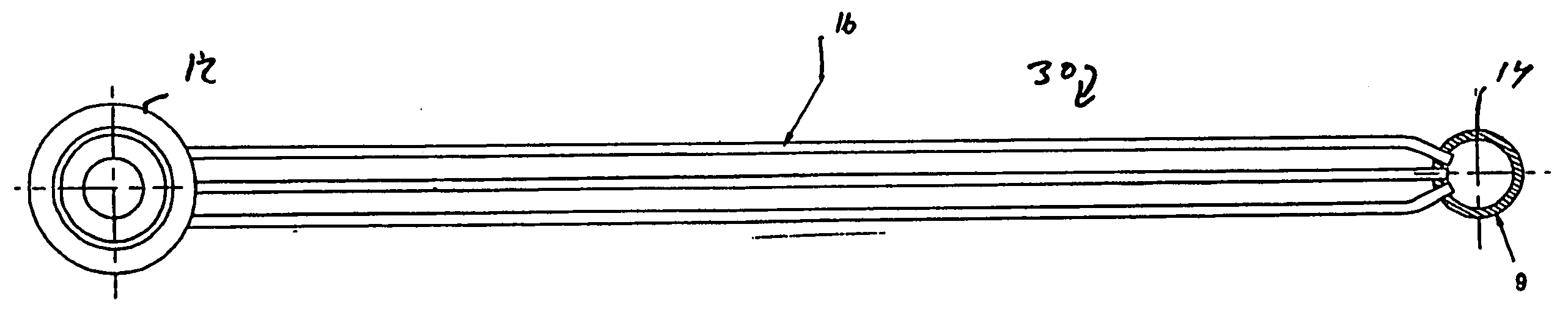
[0043] Referring to FIG. 5, an exemplary heat exchanger, such as for example, an oil cooler, is illustrated and identified at reference character 10 according to an aspect of the present teachings. The heat exchanger 10 is shown to generally include first and second end tanks 12 and 14. The end tanks 12 and 14 can be round or circular in shape. The end tanks 12 and 14 can be connected by a plurality of heat transfer tubes 16. In the exemplary illustration of FIG. 5, the heat exchanger 10 is shown to include ...


PUM


Abstract

A heat exchanger for cooling a machine fluid of a vehicle, and associated method. The heat exchanger can include a fluid inlet tank, a fluid outlet tank, and a plurality of heat transfer tubes connecting the inlet tank to the outlet tank. Each tube can include first and second substantially flat sidewalls, a plurality of internal webs extending between the first and second sidewalls, and a plurality of first dimples formed on the first sidewall, each first dimple formed over one of the webs.

Description

CROSS-REFERENCE TO RELATED APPLICATIONS [0001] This application is a continuation-in-part of U.S. patent application Ser. No. 10 / 404,015 filed on Mar. 31, 2004 which claims the benefit of U.S. Provisional Application No. 60 / 375,920 filed on Apr. 25, 2002. The disclosures of these applications are incorporated by reference herein.TECHNICAL FIELD [0002] The present invention relates to the area of cooling of the fluids that are used in machinery such as engines, transmissions and other power equipment to lubricate components and / or transfer power. INTRODUCTION [0003] In the automotive industry it is necessary to cool the oil used in automatic transmissions. The automotive transmission fluid (ATF) reaches high temperatures in the operation of the transmission. These high temperatures need to be reduced to avoid breakdown of the fluid. A device called a transmission oil cooler is conventionally used for that purpose. [0004] With reference to the simplified prior art view of FIG. 1, a ty...

Claims


Application Information

Patent Timeline
IPC IPC(8): F28D1/047F28F1/02F28F1/42F28F3/08F28F9/02
CPCF28D1/0478F28F1/022F28F2001/027F28F1/426F28F9/0234F28F1/42
Inventor MOSER, GEORGESOMMER, GORDONOSTAPOWICZ, ADAM
Owner EDC AUTOMOTIVE
Why Eureka
Try Eureka