Integrating particle rendering and three-dimensional geometry rendering

a three-dimensional geometry and particle technology, applied in the field of computer graphics animation, can solve the problems of lack of the image generated from the particle renderer cannot be composited with the image generated from the geometry renderer, and the animation does not perform as well when used to animate fuzzy and/or soft objects, etc., to achieve the effect of convenient computation, easy motion blur and depth of field effects

Inactive Publication Date: 2005-10-06
PACIFIC DATA IMAGES
View PDF5 Cites 65 Cited by
  • Summary
  • Abstract
  • Description
  • Claims
  • Application Information

AI Technical Summary

Benefits of technology

[0007] Accordingly, the invention provides computer-implemented methods and systems for compositing images from geometry renderers and particle renderers. The compositing is accomplished by incorporating geometry information from the geometry image as a number of special particles used by the particle renderer. But instead of contributing to the color and opacity of pixels in the particle-rendered image, these special particles occlude or subtract from the accumulated color and opacity of those pixels. In this way, depth resolution is done as part of the particle rendering process, and the geometry and particle images can be easily combined, for example, by alpha blending. In addition, because objects in the geometry image are treated as a number of particles, this method facilitates motion blur and depth of field effects, which are more easily computed for particles than for complex geometrical objects. Moreover, the aliasing problem can be solved by sampling the geometry image to obtain the special particles at a finer resolution than the pixel resolution of the image.

Problems solved by technology

While the three-dimensional geometry-based technique works well for solid objects, it does not perform as well when used to animate fuzzy and / or soft objects that have rich detail.
But compositing the image generated from the particle renderer with the image generated from the geometry renderer can be difficult.
This solution, however, may lead to aliasing around the silhouette of the image being composited, and it lacks support for motion blur and depth of field.

Method used


Image

  • Integrating particle rendering and three-dimensional geometry rendering
  • Integrating particle rendering and three-dimensional geometry rendering
  • Integrating particle rendering and three-dimensional geometry rendering

Examples


Embodiment Construction

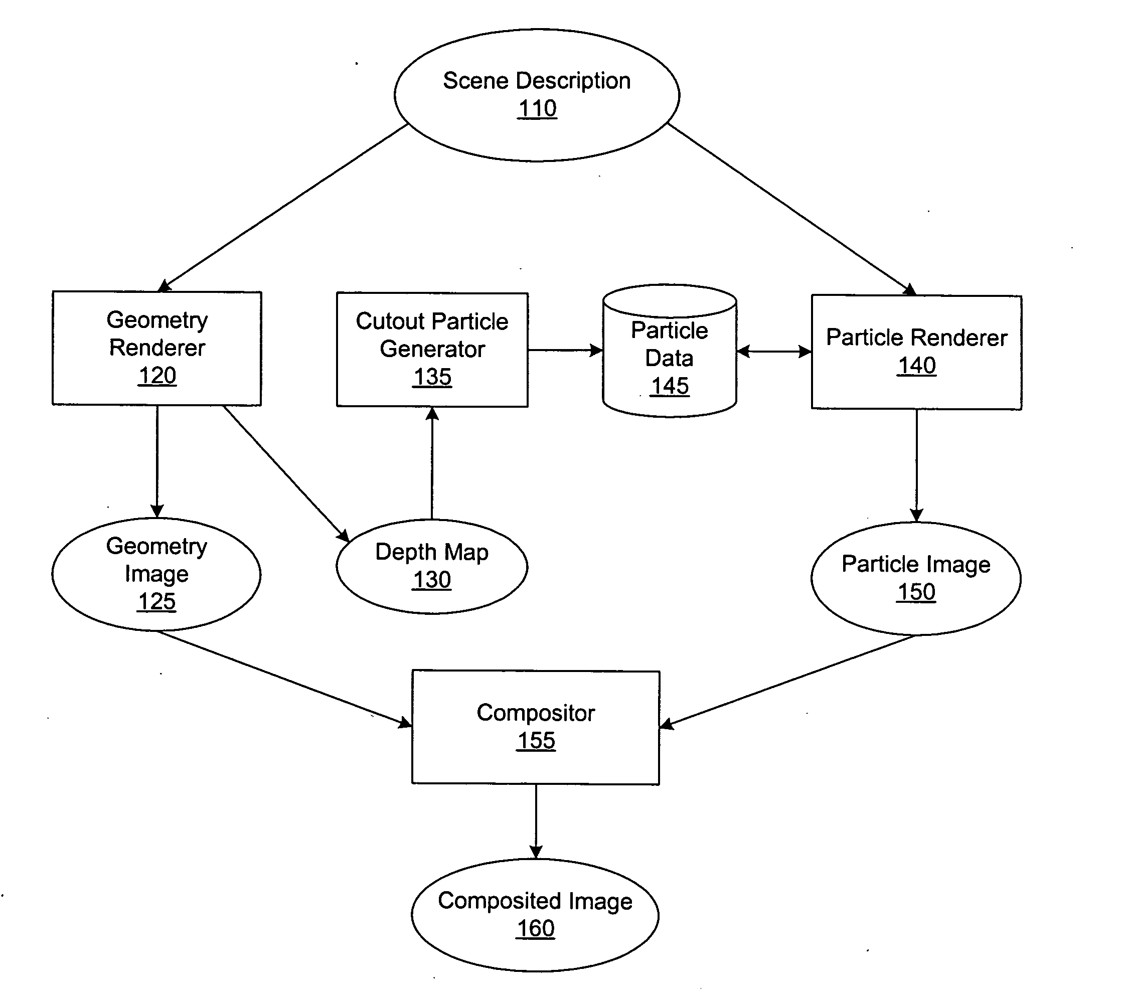
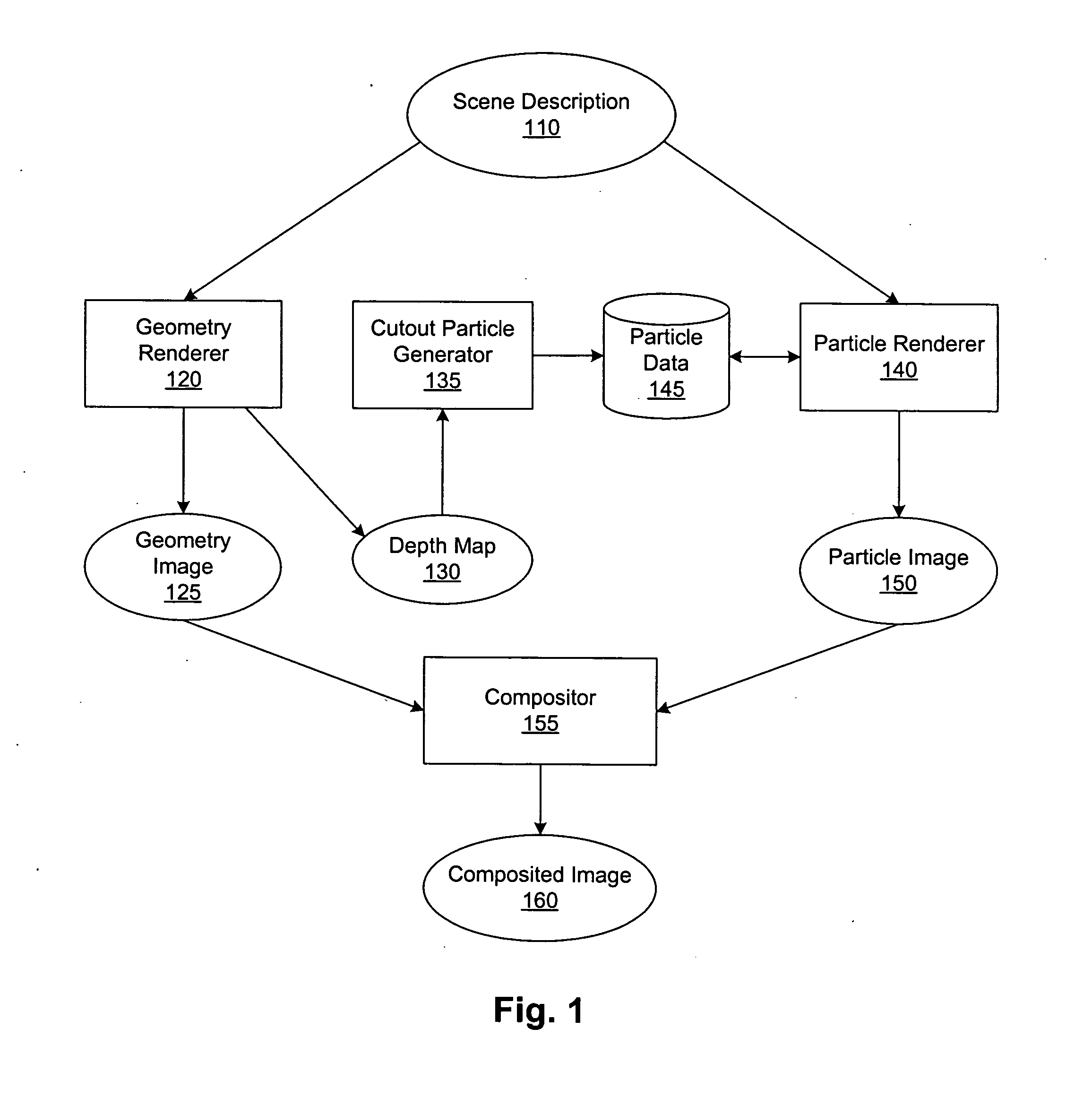
[0016] In computer animation, an animator will use various tools and methods for modeling objects in a scene and then render the images that make up the scene. The systems and methods described herein can be used, for example, when an animator desires to model some of the objects in the scene as geometric shapes and other objects as systems of particles. Accordingly, FIG. 1 illustrates a system for rendering geometry images and particle images and then compositing the images, in accordance with an embodiment of the invention. The system comprises a geometry renderer 120, a particle renderer 140, and a compositor 155, each of which can be implemented on one or more computer systems. Geometry and particle renderers are well known in the computer animation industry, and any of a variety of renderers can be used in connection with the invention. Moreover, any of the embodiments described herein or any portions thereof can be implemented in software, specialty hardware, or a combination ...


PUM


Abstract

Images from geometry renderers and particle renderers are composited by incorporating geometry information from the geometry image as a number of special cutout particles in the particle renderer. Instead of contributing to the color and opacity of pixels in the particle-rendered image, these cutout particles occlude or subtract from the accumulated color and opacity of those pixels. In this way, depth resolution is performed as part of the particle rendering process, and the geometry and particle images may be combined using a simple process such as alpha blending. In one embodiment, the cutout particles are obtained from a depth map associated with the geometry image.

Description

BACKGROUND [0001] 1. Field of the Invention [0002] The invention relates generally to computer graphics animation, and in particular, to compositing images from particle and geometry renderers. [0003] 2. Background of the Invention [0004] In the computer animation industry, images of three-dimensional scenes are often created by first constructing a three-dimensional model of the scene using modeling software. Based on the three-dimensional model, the modeling software creates surfaces for the objects in the scene by combining a number of polygons of appropriate size and shape to form the objects' surfaces. Colors are then applied to the objects by mapping a texture to these polygons. While the three-dimensional geometry-based technique works well for solid objects, it does not perform as well when used to animate fuzzy and / or soft objects that have rich detail. Such objects are often found in nature and include fire, grass, trees, and clouds. [0005] Particle systems were therefore ...

Claims


Application Information

Patent Timeline
Patent Type & Authority Applications(United States)
IPC IPC(8): G06T15/00G06T13/00G06T15/50G06T15/70
CPCG06T2210/56G06T15/503G06T13/20
Inventor XIE, FENGWEXLER, DANIEL
Owner PACIFIC DATA IMAGES
Why Eureka
Try Eureka