Communication device

Inactive Publication Date: 2005-10-06
MITSUBISHI ELECTRIC CORP
View PDF5 Cites 4 Cited by
  • Summary
  • Abstract
  • Description
  • Claims
  • Application Information

AI Technical Summary

Benefits of technology

[0010] Therefore, the aspect of the present invention offers an advantage of being able to eliminate the need for special-purpose hardware used for setting up an arrangement channel and another advantage of being able to implement the arrangement channel by using the communication apparatus having a simplified hardware structure.
[0012] Therefore, the other aspect of the present embodiment offers an advantage of being able to implement an arrangement channel by using the communication apparatus having a simplified hardware structure, and another advantage of being able to perform routing of the arrangement channel.
[0014] Therefore, the further aspect of the present embodiment offers an advantage of being able to implement an arrangement channel by using either a general-purpose handset, or a microphone and a speaker.

Problems solved by technology

A problem with a prior art communication apparatus constructed as above is that since it needs to be provided with an arrangement channel control unit intended for control in order to implement an arrangement channel, a special-purpose unit needs to be provided.
Another problem is that since the physical interface between the arrangement channel control unit and the multiplexing transmission unit has a special structure for each type of unit provided with an arrangement channel control unit, the multiplexing transmission unit needs to have a special-purpose interface intended for arrangement channels.

Method used


Image

  • Communication device
  • Communication device
  • Communication device

Examples


embodiment 1

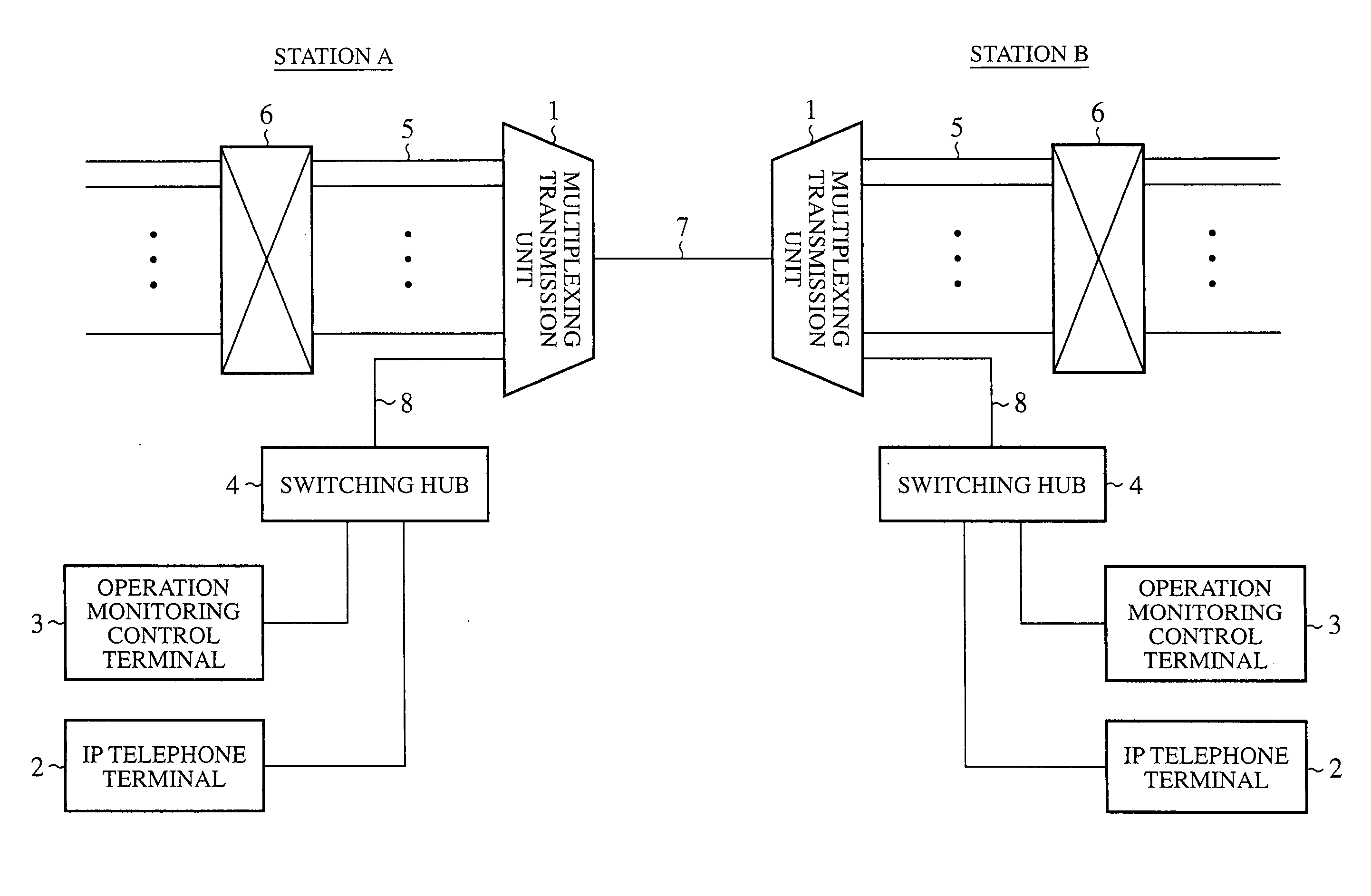
[0023]FIG. 1 is a block diagram showing the structure of a communication apparatus in accordance with embodiment 1 of the present invention. FIG. 1 shows the structures of a station A and another station B which are disposed opposite to each other. The communication apparatus at each of the two stations is provided with a multiplexing transmission unit 1, an IP (Internet Protocol) telephone terminal 2, an operation monitoring control terminal 3, and a switching hub 4. An exchange 6 is connected to the multiplexing transmission unit 1 of each of the two communication apparatus by way of a primary channel group 5. A bearer channel 7 having an STM network interface connects between the multiplexing transmission units 1 of the two stations, and the multiplexing transmission units 1 are transmission units which comply with an STM network.

[0024] The operation monitoring control terminal 3 is connected, via the switching hub 4, to the multiplexing transmission unit 1 by an Ethernet (regis...

embodiment 2

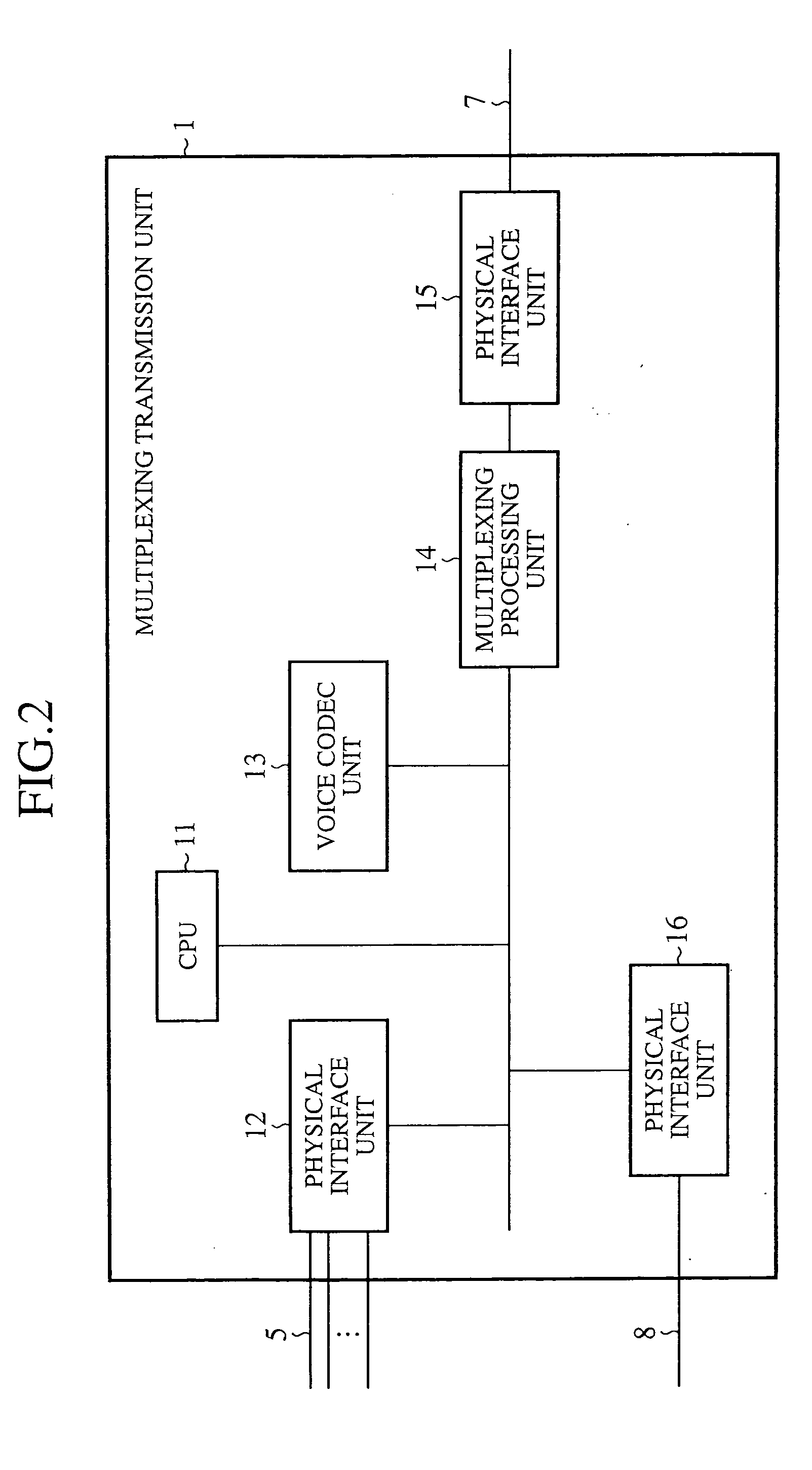
[0043]FIG. 5 is a block diagram of a communication apparatus in accordance with this embodiment 2. The same components as those shown in FIG. 1 are designated by the same reference numerals as shown in FIG. 1, and the explanation of the components will be omitted hereafter. In FIG. 5, only the structure of a station A is illustrated. A multiplexing transmission unit 1 has a structure shown in FIG. 2, and an IP telephone terminal 2 has a structure shown in FIG. 3.

[0044] In the communication apparatus in accordance with embodiment 1, the IP telephone terminal 2 and the operation monitoring control terminal 3 share a physical interface and are connected to the multiplexing transmission unit 1 via the switching hub 4, as previously mentioned. In contrast, the communication apparatus in accordance with this embodiment 2 is so constructed that an IP telephone terminal 2 is connected to an operation monitoring control terminal 3 and the operation monitoring control terminal 3 is further c...

embodiment 3

[0051]FIG. 7 is a block diagram of an operation monitoring control terminal 3 of a communication apparatus in accordance with embodiment 3 of the present invention. The communication apparatus of this embodiment 3 is provided with a handset 51, instead of the IP telephone terminal 2 of embodiment 2. As shown in FIG. 7, the operation monitoring control terminal 3 is provided with a voice CODEC unit 34 and an A / D converter 35. The same components as those shown in FIG. 6 are designated by the same reference numerals as shown in FIG. 6, and the explanation of the components will be omitted hereafter. The handset 51 is connected to the A / D converter 35 of the operation monitoring control terminal 3. The handset 51 is provided with a microphone and a speaker which are not shown in FIG. 7.

[0052] Next, a flow of a signal via an arrangement channel will be explained.

[0053] When a maintenance person inputs voice into the handset 51, the A / D converter 35 digitizes an analog signal from the ...


PUM


Abstract

A communication apparatus includes a multiplexing transmission unit (1) for multiplexing and transmitting communication data, an operation monitoring control terminal (3) for monitoring the multiplexing transmission unit (1), and an IP terminal (2) connected with the multiplexing transmission unit (1) by way of a physical interface between the multiplexing transmission unit (1) and the operation monitoring control terminal (3) which the IP terminal shares with the operation monitoring control terminal, the IP terminal converting a signal inputted to the communication apparatus from outside into IP packets, and furnishing them to the multiplexing transmission unit (1). The multiplexing transmission unit (1) multiplexes the IP packets furnished thereto from the IP terminal (2) and communication data, and then transmits them to a station which is disposed opposite to the communication apparatus.

Description

FIELD OF THE INVENTION [0001] The present invention relates to a communication apparatus which is used for digital communications, and which implements an arrangement channel by means of a multiplexing transmission unit which efficiently transmits voice, data, FAX signals, etc. BACKGROUND OF THE INVENTION [0002] A multiplexing transmission unit is a unit that is installed between exchanges in order to use channels more effectively, and that compresses and multiplexes voice signals transmitted thereto via many channels by using a voice coding technology and a soundless compression technology (DSI: Digital Speech Interpolation), and efficiently transmits the multiplexed voice signals by way of a small number of channels. A multiplexing transmission unit is installed in each of a receive side and a transmit side, and the multiplexing transmission unit on the receive side decompresses and demultiplexes signals compressed and multiplexed by the multiplexing transmission unit on the trans...

Claims


Application Information

Patent Timeline
Patent Type & Authority Applications(United States)
IPC IPC(8): H04BH04J3/14H04J3/24H04L12/56
CPCH04J3/247
Inventor HARADA, YOSHIHISA
Owner MITSUBISHI ELECTRIC CORP
Why Eureka
Try Eureka