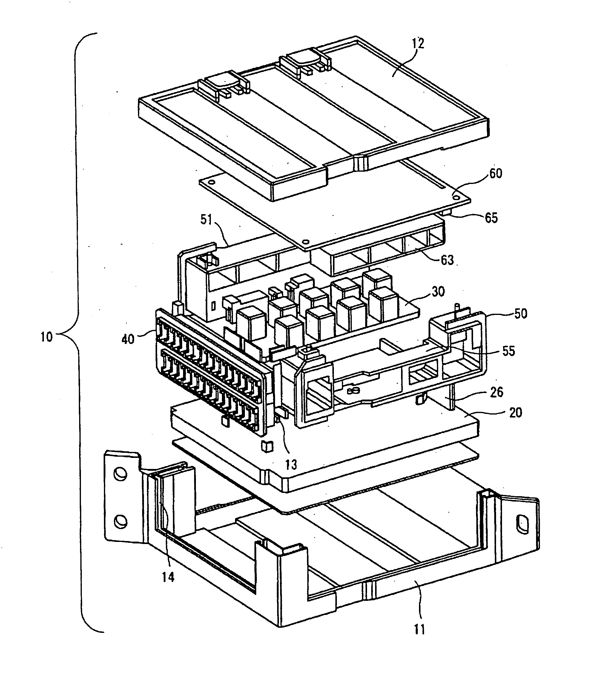
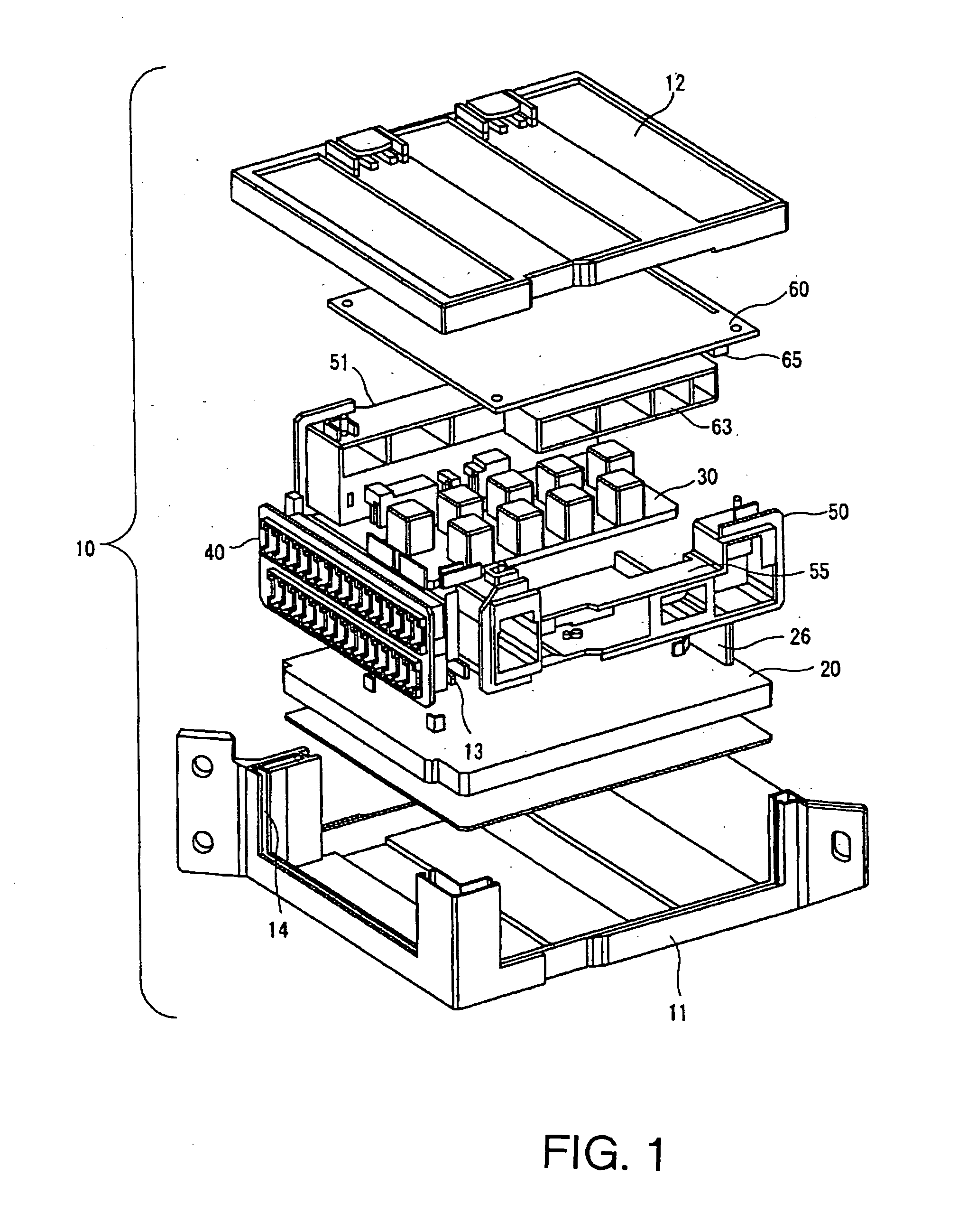
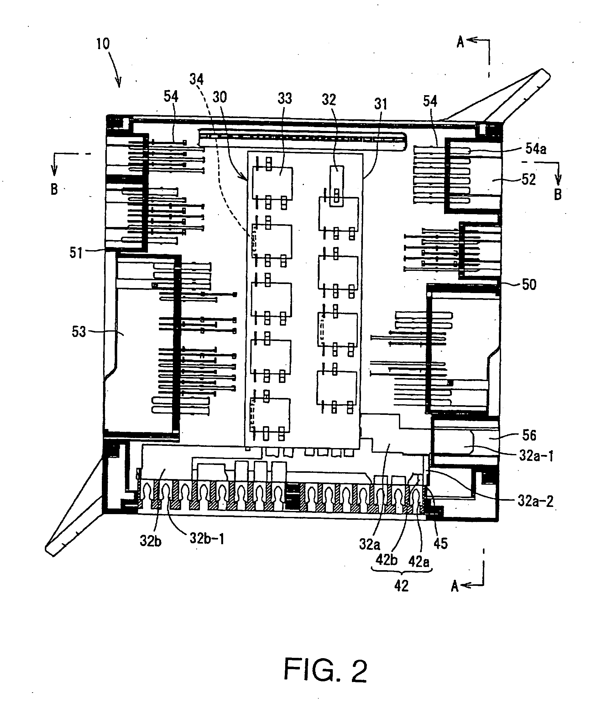
Automotive relay and electrical connector box
a technology for automotive electrical connectors and relays, which is applied in the directions of relays, electromagnetic relay details, transportation and packaging, etc., can solve the problems of unnecessarily large use of relays and connector boxes made to unnecessarily large sizes, inability to provide sufficient crush space, and limited space within the instrument panel
- Summary
- Abstract
- Description
- Claims
- Application Information
AI Technical Summary
Benefits of technology
Problems solved by technology
Method used
Image
Examples
first embodiment
[0066]FIGS. 9A and 9B describe a modified version of the first embodiment wherein bent parts of the two leads 34a of resistor 34 are welded to the upper sides of terminals 33c that project from relay body 33a. With leads 34a of resistor 34 welded to terminals 33c, the lower sides of terminals 33c of common relay 33 are then welded to bus bar 32, thereby forming a common location where leads 34a of resistor 34, terminals 33c of common relay 33, and bus bar 32 are welded together.
second embodiment
[0067]FIGS. 10A and 10B describe the present invention wherein leads 34a of resistor 34 are welded to bus bar 32 which is fixedly attached to insulator board 31 of relay module 30, after which terminals 33c of common relay 33 are welded to the location where leads 34a have been welded to bus bar 32. This construction eliminates the need to provide a separate space for the connection of leads 34a of resistor 34, and results in a more compact design.
third embodiment
[0068]FIGS. 11A and 11B describe the present invention wherein terminals 33c of common relay 33 and leads 34a of resistor 34 are connected through L-shaped common-use bus bars 35. Terminals 33c of common relay 33 are welded to end 35a of bus bar 35, and friction connector 35b, which is formed on the other end of bus bar 35, is frictionally connected to leads 34a of resistor 34. As described above, terminals 33c of common relay 33 and leads 34a of resistor 34 are connected through L-shaped common-use bus bars 35, after which L-shaped common-use bus bars 35 are welded to bus bar 32 which is fixedly attached to insulator board 31 of relay module 30.
[0069] Due to the above described structure allowing the connection of leads 34a of resistor 34 to terminals 33c of common relay 33 through common-use bus bar 35 before the assembly of electrical connector box 10, only terminals 33c of common relay 33 need be welded to bus bar 32 of the internal circuit, thus making the assembly of electrica...
PUM
 Abstract
Description
Claims
Application Information
 - R&D
- Intellectual Property
- Life Sciences
- Materials
- Tech Scout
- Unparalleled Data Quality
- Higher Quality Content
- 60% Fewer Hallucinations
Browse by: Latest US Patents, China's latest patents, Technical Efficacy Thesaurus, Application Domain, Technology Topic, Popular Technical Reports.
© 2025 PatSnap. All rights reserved.Legal|Privacy policy|Modern Slavery Act Transparency Statement|Sitemap|About US| Contact US: help@patsnap.com


