
Protection device in motor vehicles for protecting individuals

a protection device and motor vehicle technology, applied in the directions of vehicle safety arrangements, pedestrian/occupant safety arrangements, transportation and packaging, etc., can solve the problems of severe injuries, incorrect function tracing back, and head and upper body of adult pedestrians or bicycle riders, and achieve significant cost advantages, simple realization, and thin cross section of material

Inactive Publication Date: 2010-07-08
ISE AUTOMOTIVE
View PDF9 Cites 5 Cited by
  • Summary
  • Abstract
  • Description
  • Claims
  • Application Information

AI Technical Summary

Benefits of technology

[0018]Smaller pyrotechnic charges can be used, which has the result that lighter materials with thinner material cross sections can be selected. This leads, in turn, to significant cost advantages.
[0019]The pyrotechnic release and deployment system is very simple to realize and very resistant to incorrect releases.
[0020]The movable element experiences a high kinetic energy after only a few millimeters of extension displacement. Therefore, on the one hand, it is deployed very quickly and, on the other hand, it can punch through a rear window located in the erection path for use in a convertible with a closed roof, in order to reach the full erection travel.

Problems solved by technology

Here, in particular, the head as well as the upper body of an adult pedestrian or bicycle rider is put at risk, because upon an impact with a motor vehicle—as crash tests and also experience have shown—these parts hit approximately in the rear, relatively hard area on the front hood at the transition to the windshield and in this way can be severely injured.
The use of several components, which form the holding device, can result in incorrect function tracing back to an addition of the different tolerances.
In addition, it can involve an expensive embodiment; due to pressure on costs in the automotive supplier industry.
However, the call for economical systems becomes louder and louder.

Method used


Image

  • Protection device in motor vehicles for protecting individuals
  • Protection device in motor vehicles for protecting individuals
  • Protection device in motor vehicles for protecting individuals

Examples


Embodiment Construction

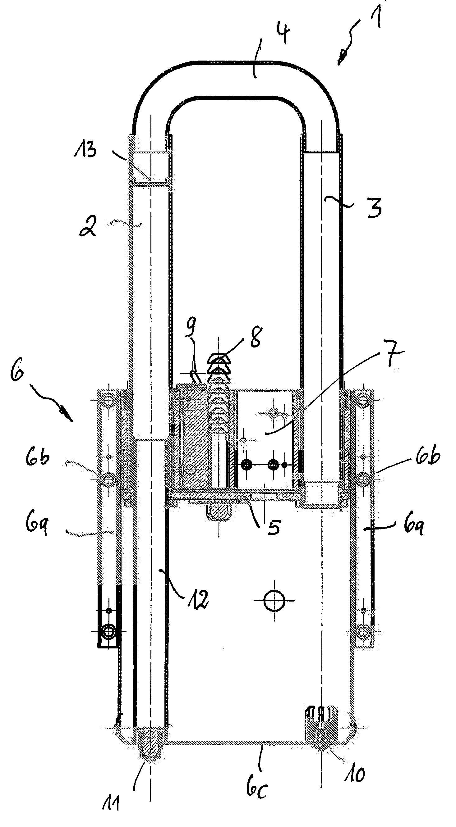
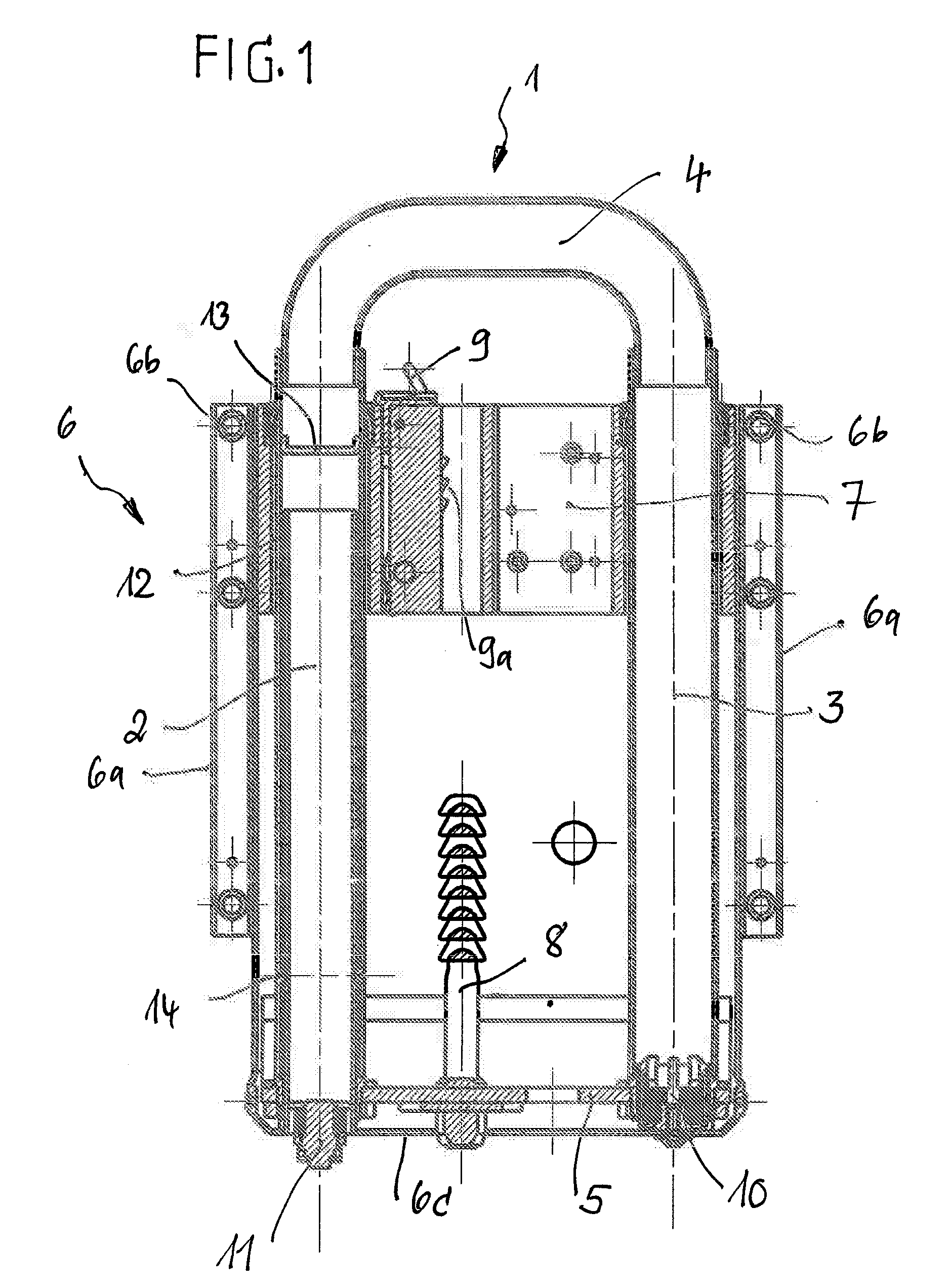
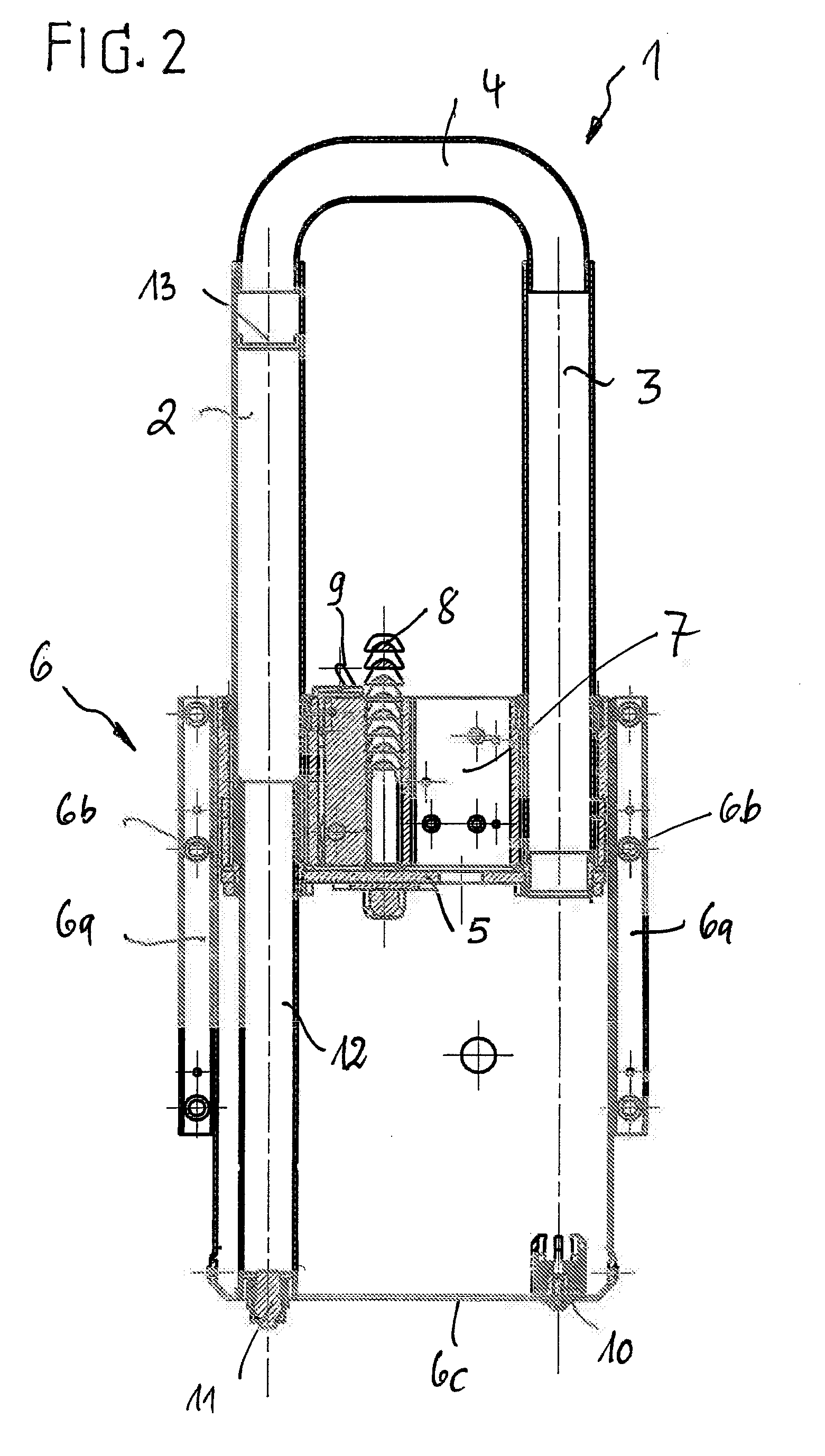
[0030]In FIGS. 1 to 7 the drawings show embodiments of the protection device according to the invention in the form of an active rollover protection system for protecting occupants in a convertible, in which the movable element is formed by a U-shaped rollover bar 1 with two parallel, tubular legs 2, 3 and a curved tubular crosspiece 4. The free ends of the legs 2, 3 are here connected in a reinforcing way by a traverse 5.

[0031]The rollover bar 1 is held in a guided way in a cartridge-like housing 6, which has side walls 6a with attachment holes 6b and a base 6c. For this purpose, in the upper region of the housing 6, a guide block 7 is attached that has guide openings for the legs 2, 3. On the traverse 5 a catch pin 8 is attached that connects to a catch hinged in the guide block so that it can rotate. Of these components, in the Figs., only the unlocking lever arm 9, to be activated manually, and also the teeth 9a for an active engagement with the undercut sections on the catch pi...


PUM


Abstract

Protection devices in motor vehicles typically have a movable element, for example a roll bar (1) or a flap, which, in the initial state, is fixed in its position by a releasable holding device. In the event of a hazard, the movable element can be released under sensor control by a common pyrotechnic actuator (11) and can be deployed with the protection being activated. The protection device also has a means (8, 9) for locking the deployed, movable element. A driving pressure chamber (12, 15), which is fixed on the bodywork and in which a driving piston (2 with 13, 16) connected to the movable element is accommodated in a guided manner, is connected downstream of the pyrotechnic actuator (11). The protection device is designed with regard to the pyrotechnic release and erecting system in such a manner that, with as small a pyrotechnic charge as possible and a defined holding force which is not applied by additional holding elements, the movable element can obtain a very high kinetic energy even after just a few millimeters of extension travel. To accomplish this, a releasable connection is formed by a locally delimited, frictional and / or form-fitting and / or bonding direct connection (14) between the wall of the driving pressure chamber (12, 15) and the driving piston (2 with 13, 16). The direct connection has a releasable holding force which amounts to at least 300 N and at maximum 5000 N.

Description

CROSS-REFERENCE TO RELATED APPLICATIONS[0001]This application is a Section 371 of International Application No. PCT / EP2007 / 053250, filed Apr. 3, 2007, which was published in the German language on Oct. 11, 2007, under International Publication No. WO 2007 / 113303 A1 and the disclosure of which is incorporated herein by reference.BACKGROUND OF THE INVENTION[0002]The invention relates to a protection device in motor vehicles for protecting individuals, which has a movable element that, in its initial state, is fixed in its position by a releasable holding device formed by a releasable connection of the movable element to the vehicle. In the event of a dangerous situation, the protection device can be released under the control of sensors by a common pyrotechnic actuator and deployed with activation of the protection. The protection device has a device for locking the deployed, movable element, wherein a drive pressure chamber fixed to the vehicle by its walls is connected after the pyr...

Claims


Application Information

Patent Timeline
Patent Type & Authority Applications(United States)
IPC IPC(8): B60R21/13B60R21/02
CPCB60R2021/135B60R21/13
Inventor ROHNER, STEPHANJANISCH, MIRKOLANG, JOZEFSCHULTE, MICHAELMENNE, HANS GERDLIESAUS, FRANK
Owner ISE AUTOMOTIVE
Learn More