

Electrical connector box
a technology of electrical connectors and boxes, applied in the direction of multiple connection subassemblies, electrical apparatus, printed circuits, etc., can solve the problem that no effort has been made to form the electrical connector boxes to thin cross sections
- Summary
- Abstract
- Description
- Claims
- Application Information
AI Technical Summary
Benefits of technology
Problems solved by technology
Method used
Image

Examples
Embodiment Construction
[0033] The particulars shown herein are by way of example and for purposes of illustrative discussion of the embodiments of the present invention only and are presented in the cause of providing what is believed to be the most useful and readily understood description of the principles and conceptual aspects of the present invention. In this regard, no attempt is made to show structural details of the present invention in more detail than is necessary for the fundamental understanding of the present invention, the description is taken with the drawings making apparent to those skilled in the art how the forms of the present invention may be embodied in practice.
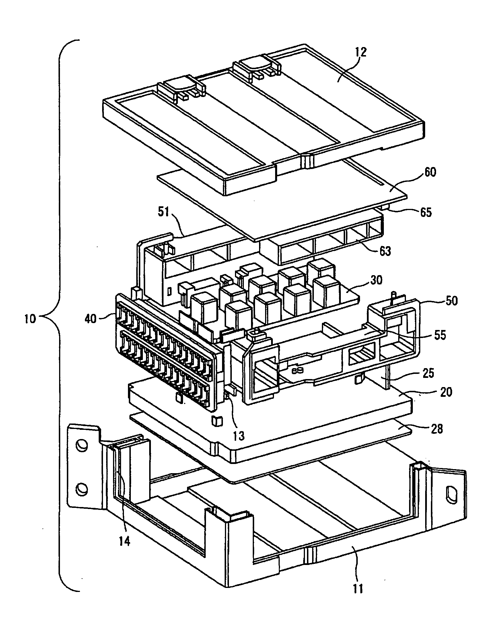
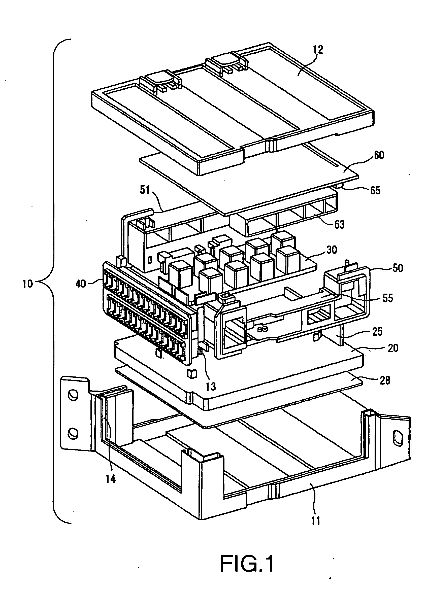
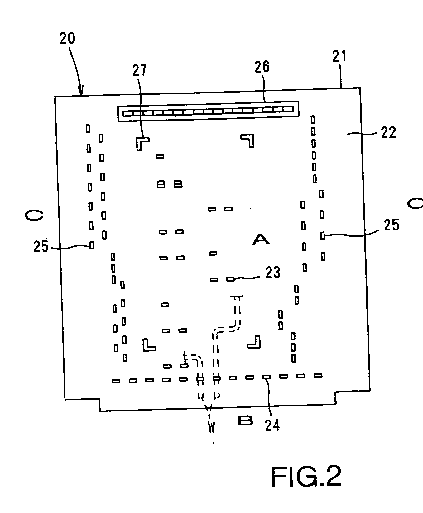
[0034] The following will describe an embodiment of the invention with reference to the drawings. FIGS. 1 through 6 describe an embodiment of the present invention including an electrical connector box 10 in which internal circuit block 20 is located above lower case 11, relay module 30 is located above internal circuit bloc...
PUM
 Abstract
Description
Claims
Application Information