
Vehicle transmission control system

Inactive Publication Date: 2005-10-06
JATCO LTD
View PDF10 Cites 4 Cited by
  • Summary
  • Abstract
  • Description
  • Claims
  • Application Information

AI Technical Summary

Benefits of technology

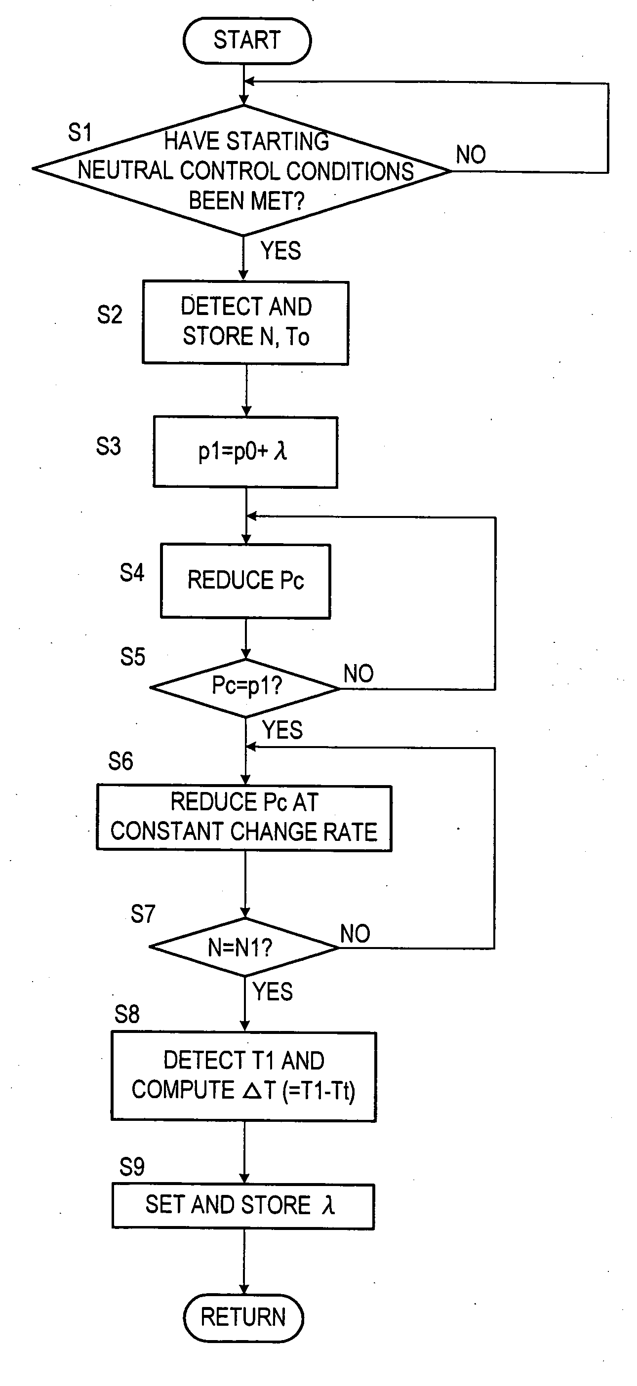
[0003] Feedback control is often performed during neutral control. In feedback control, the amount of time it takes from a point at which the clutch pressure reduction begins, up to a point at which the rotation speed of a turbine runner (turbine rotation speed) reaches a predetermined rotation speed, is made constant over different automatic transmission operation states. Correction values are computed based on the difference between a target value and the actual amount of time needed for the turbine rotation speed to reach the predetermined rotation speed. The correction values are then used to enhance control performance in subsequent clutch pressure reductions. Each of the correction values is stored in a memory in association with the operation state of the automatic transmission at the point where the turbine rotation speed reaches the predetermined rotation speed and the correction value is set.

Problems solved by technology

With this method, however, correction values are not stored in correct regions of the memory if different automatic transmission operation states exist at the point where the clutch pressure reduction begins and at the point where the correction values are set and stored.
Appropriate correction values cannot be obtained when the correction values are not stored in the appropriate regions, and this makes it difficult to perform control so that the actual amount of time necessary becomes equal to the target value.

Method used


Image

  • Vehicle transmission control system
  • Vehicle transmission control system
  • Vehicle transmission control system

Examples


Embodiment Construction

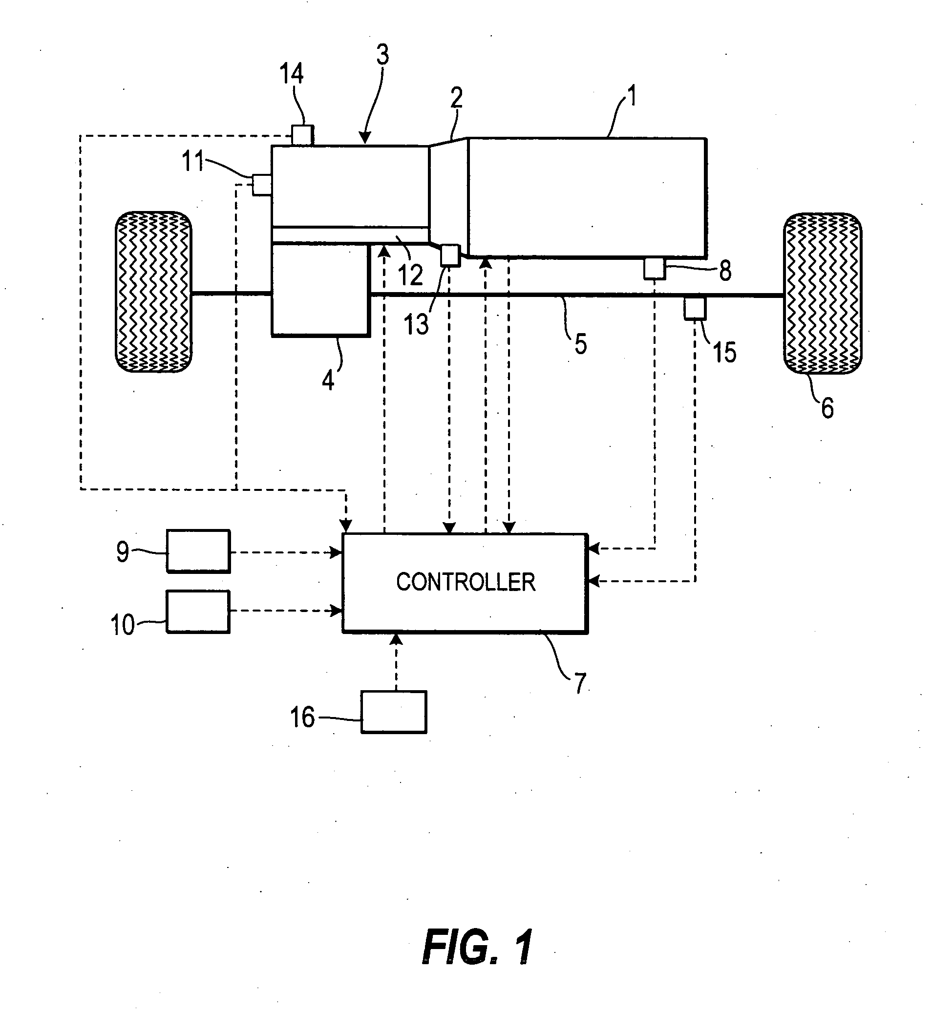
[0015]FIG. 1 is a block diagram of a transmission control system according to this invention. Rotation of an engine 1 is transmitted to an automatic transmission 3. The rotation is transmitted to drive wheels 6, through a differential gear unit 4, and a drive shaft 5, after undergoing a speed change by the automatic transmission 3. The automatic transmission 3 comprises a torque converter 2, and a hydraulic pressure circuit 12 that regulates the hydraulic pressure supplied to constituent elements of the automatic transmission 3.

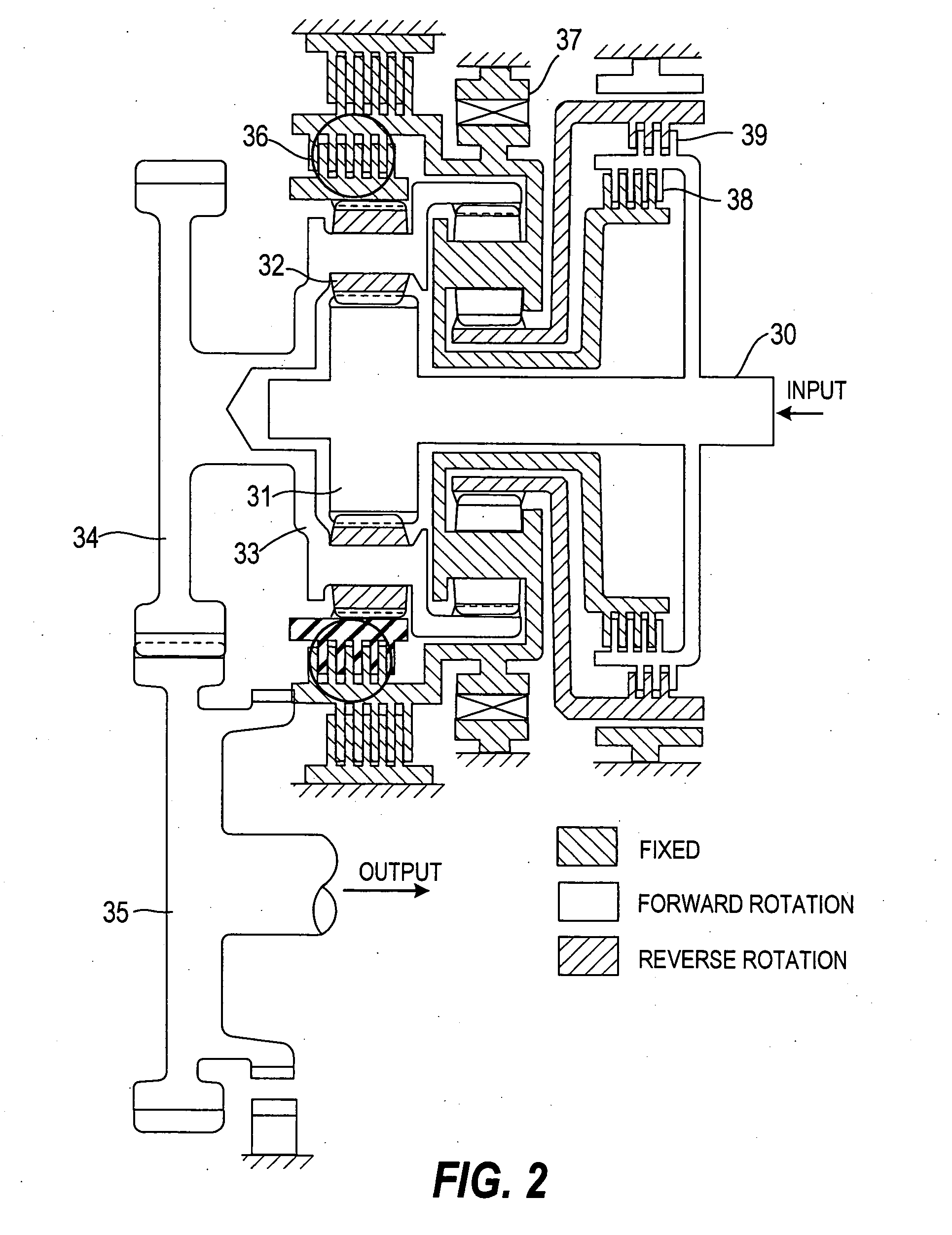
[0016]FIG. 2 is a block diagram of portions other than the torque converter 2 of the automatic transmission 3. FIG. 2 shows a state of the automatic transmission 3 when a running range such as a drive (D) range, a second gear (2) range, or a low (L) range is selected. Power input to an input shaft 30 is transmitted to a planetary gear 32 through a sun gear 31 of a planetary gear mechanism provided in an end portion of the input shaft 30. The power transmitte...


PUM


Abstract

Clutch pressure is reduced to an initial pressure, and a transmission operation state is stored, when a vehicle is stopped with an engine in an idling state. The clutch pressure is further reduced at a constant change rate and the amount of time is measured until the turbine rotation speed increases to the predetermined rotation speed. Based on the measured amount of time, a correction amount is computed for the initial pressure necessary to increase the turbine rotation speed to the predetermined rotation speed in a predetermined amount of time. The correction amount is stored in a memory region corresponding to the transmission operation state when the clutch pressure is reduced to the initial pressure. The initial pressure is corrected according to the correction amount stored in the memory region corresponding to the transmission operation state when the clutch. pressure is reduced.

Description

FIELD OF THE INVENTION [0001] This invention relates to a transmission control system used in a vehicle. BACKGROUND OF THE INVENTION [0002] JP2003-74683A, published by the Japan Patent Office in 2003, discloses neutral control that reduces hydraulic pressure supplied to an automatic transmission clutch to maintain the clutch in a state immediately prior to engagement when a vehicle is stopped in an engine idling state. SUMMARY OF THE INVENTION [0003] Feedback control is often performed during neutral control. In feedback control, the amount of time it takes from a point at which the clutch pressure reduction begins, up to a point at which the rotation speed of a turbine runner (turbine rotation speed) reaches a predetermined rotation speed, is made constant over different automatic transmission operation states. Correction values are computed based on the difference between a target value and the actual amount of time needed for the turbine rotation speed to reach the predetermined ...

Claims


Application Information

Patent Timeline
IPC IPC(8): F16H61/20F16H61/686F16H59/38F16H61/04F16H61/00
CPCF16H61/20F16H2059/385F16H2312/022F16H2061/207Y10T477/6395Y10T477/6414Y10T477/653Y10T477/6939
Inventor AKAIKE, TSUTOMU
Owner JATCO LTD
Learn More