IOL injector

a technology of iol and injector, which is applied in the field of ophthalmic surgical devices and methods, can solve the problems of reducing the likelihood that the iol can be wedged between the plunger tip and the plunger, and achieves the effect of reducing the force required to advance the iol therethrough, and reducing the chance of iol damag

Active Publication Date: 2005-10-06
BAUSCH & LOMB INC
View PDF12 Cites 88 Cited by
  • Summary
  • Abstract
  • Description
  • Claims
  • Application Information

AI Technical Summary

Benefits of technology

[0009] The injector comprises a device body having a longitudinal passageway (lumen) defined by an inner passageway wall terminating at an open tip. A plunger having a longitudinal plunger shaft and a plunger tip telescopes with the lumen of the device body. A loading bay is located in the lumen wherein an IOL is positioned and compressed. In a first aspect of the invention, the lumen increases in diameter from a point adjacent the loading bay to the open tip. This allows the IOL to gradually expand as it is advanced through the passageway by the plunger tip. This reduces forces on the IOL and thus reduces the chance of IOL damage caused by excessive forces exerted thereon during IOL delivery through and out the device. At the same time, the outer diameter of the device body along the same length remains constant at the desired diameter (e.g., sub 3 mm) so that the eye incision size need not be increased even though the inner diameter of the passageway is increasing. It will be appreciated that a compressed IOL will naturally seek a position of less compressive force. Thus, once the IOL is initially advanced by the plunger, the increasing diameter of the passageway adjacent the loading bay urges the IOL to continue to move in that direction (i.e., toward the open tip). The amount of force required to advance the IOL therethrough is thereby reduced and the goal of less force on the IOL during delivery through the inserter device is realized.
[0010] In another aspect of the invention, the cross-sectional shape of the plunger tip is substantially the same as the cross-sectional shape and slightly smaller than the diameter of the inner wall defining the lumen along the length where the IOL travels. As such, the plunger tip is in close, sliding relation to the passageway. This reduces the likelihood that the IOL can become wedged between the plunger tip and the passageway wall, a problem of prior injector designs having relatively large spacing between the plunger tip and inner lumen wall.

Problems solved by technology

This reduces the likelihood that the IOL can become wedged between the plunger tip and the passageway wall, a problem of prior injector designs having relatively large spacing between the plunger tip and inner lumen wall.

Method used


Image

  • IOL injector
  • IOL injector
  • IOL injector

Examples


Embodiment Construction

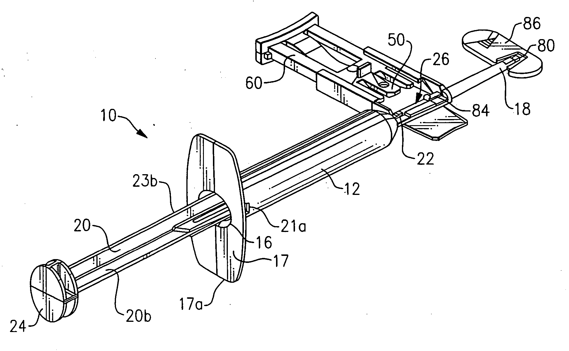
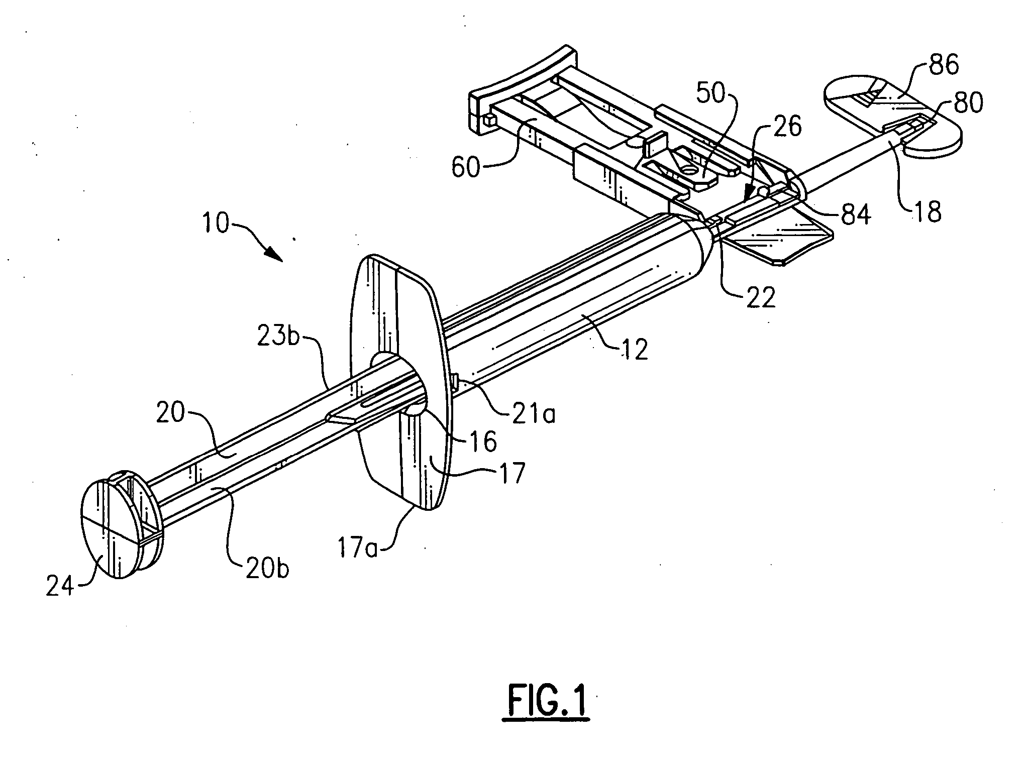
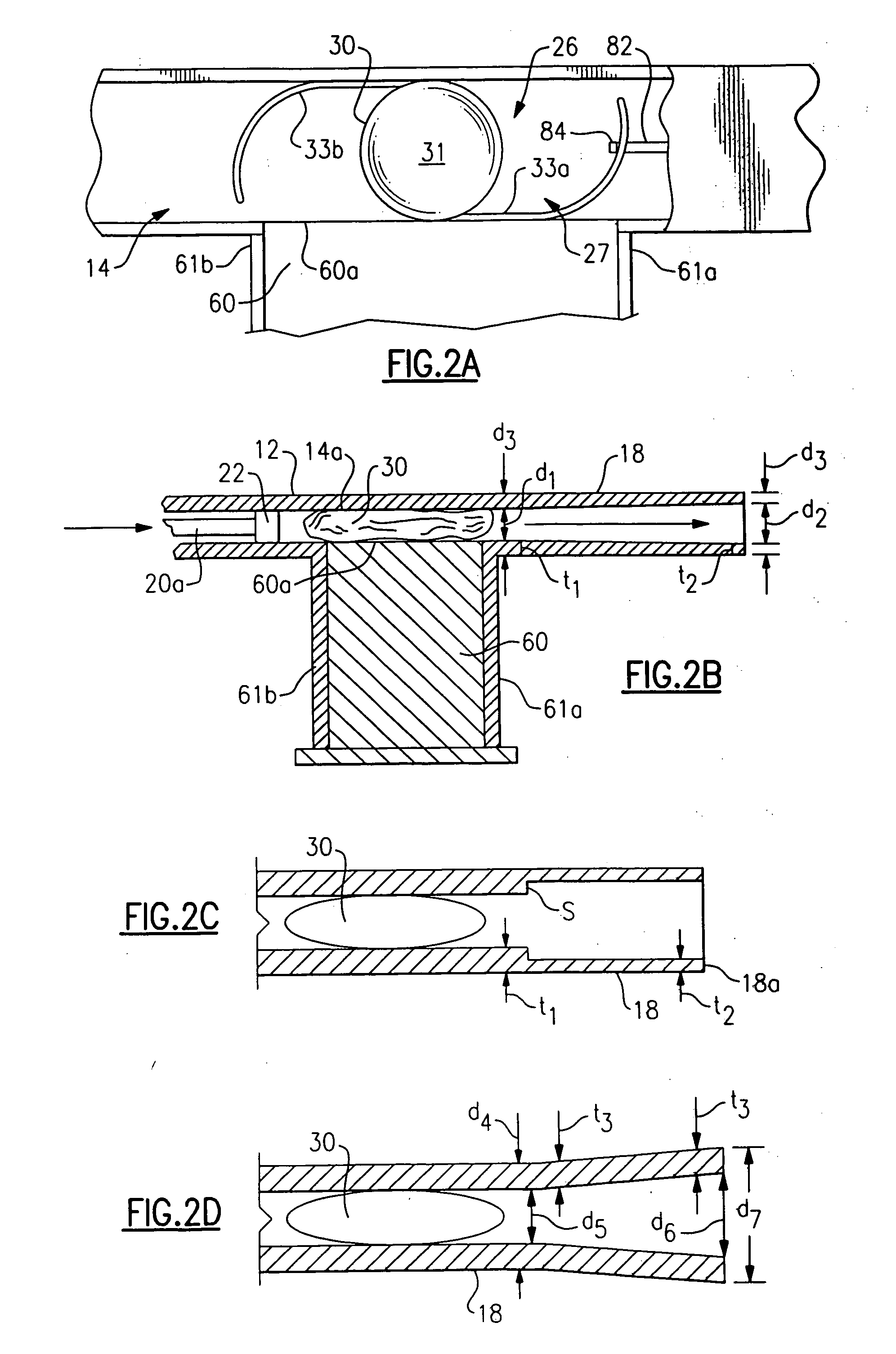
[0022] Referring to the Figures, a representative IOL injector device is indicated generally by the reference numeral 10. The injector device 10 includes an injector body 12 having a longitudinal lumen 14 extending from the proximal end 16 to distal end 18 thereof. The lumen may assume any desired cross-sectional shape although circular or oval shapes are preferred. Proximal end 16 may include a finger hold flange 17 preferably configured with a straight edge 17a as shown for resting device 10 on a flat surface. A plunger 20, having distal and proximal lengths 20a, 20b, respectively, and a distal plunger tip 22 (see FIG. 2A) and proximal thumb press 24, telescopes within lumen 14 for engaging and pushing the IOL 30 through lumen 14 and out of distal tip 18a. The IOL delivery sequence will be explained in more detail below. It is understood that the overall configuration of the injector body 12 may vary from that shown and described herein. It is furthermore understood that the compo...


PUM


Abstract

A device for injecting an intraocular lens (IOL) into an eye, the device having an injector body including a lumen and an open tip wherethrough the IOL is expressed from the device. An IOL loading bay is located in the passageway wherein the IOL is positioned and compressed. In a first aspect of the invention, the passageway diameter increases from a point adjacent the loading bay to the open tip to reduce compressive force on the IOL as it travels through the lumen. In another aspect of the invention, the plunger tip has a shape and diameter which has a close, sliding fit with the shape and diameter of the passageway to reduce the chance of the IOL becoming wedged between the plunger tip and the passageway wall as the plunger tip engages and advances the IOL through the passageway.

Description

BACKGROUND OF THE INVENTION [0001] The present invention relates to ophthalmic surgical devices and methods. More particularly, the present invention relates to a device and method for inserting an intraocular lens (IOL) into an eye. [0002] IOLs are artificial lenses used to replace the natural crystalline lens of the eye when the natural lens has cataracts or is otherwise diseased. IOLs are also sometimes implanted into an eye to correct refractive errors of the eye in which case the natural lens may remain in the eye together with the implanted IOL. The IOL may be placed in either the posterior chamber or anterior chamber of the eye. IOLs come in a variety of configurations and materials. Some common IOL styles include the so-called open-looped haptics which include the three-piece type having an optic and two haptics attached to and extending from the optic; the one-piece type wherein the optic and haptics are integrally formed (e.g., by machining the optic and haptics together f...

Claims


Application Information

Patent Timeline
Patent Type & Authority Applications(United States)
IPC IPC(8): A61F2/00A61F2/16
CPCA61F2/1678A61F2002/30217A61F2230/0067
Inventor VAQUERO, EDWARD
Owner BAUSCH & LOMB INC
Why Eureka
Try Eureka